


Quick Research
Generate reliable direction feasibility study reports for your R&D in just a few steps.

Technical Q&A
Discover and master advanced knowledge NOW. Basics, ideas, possibilities, all at once.

Find Solutions
As an expert in R&D theories, this can generate solutions to your technical problems instantly.

Evaluate Feasibility
Analyze your overall solution with one click, know your potential R&D risks in advance.

Monitor Landscape
Get weekly tech updates, stay abreast of the latest tech innovations and key insights.
Rapid wet plugging electric connection structure
A technology of electrical connection structure and wet plugging, applied in the direction of connection, two-part connection device, parts of connection device, etc., can solve problems such as easy misoperation, equipment damage, contact pin electrolysis or short circuit, etc., and achieve high positioning accuracy Effect
- Summary
- Abstract
- Description
- Claims
- Application Information
AI Technical Summary
Problems solved by technology
Method used
Image

Examples
Embodiment 1
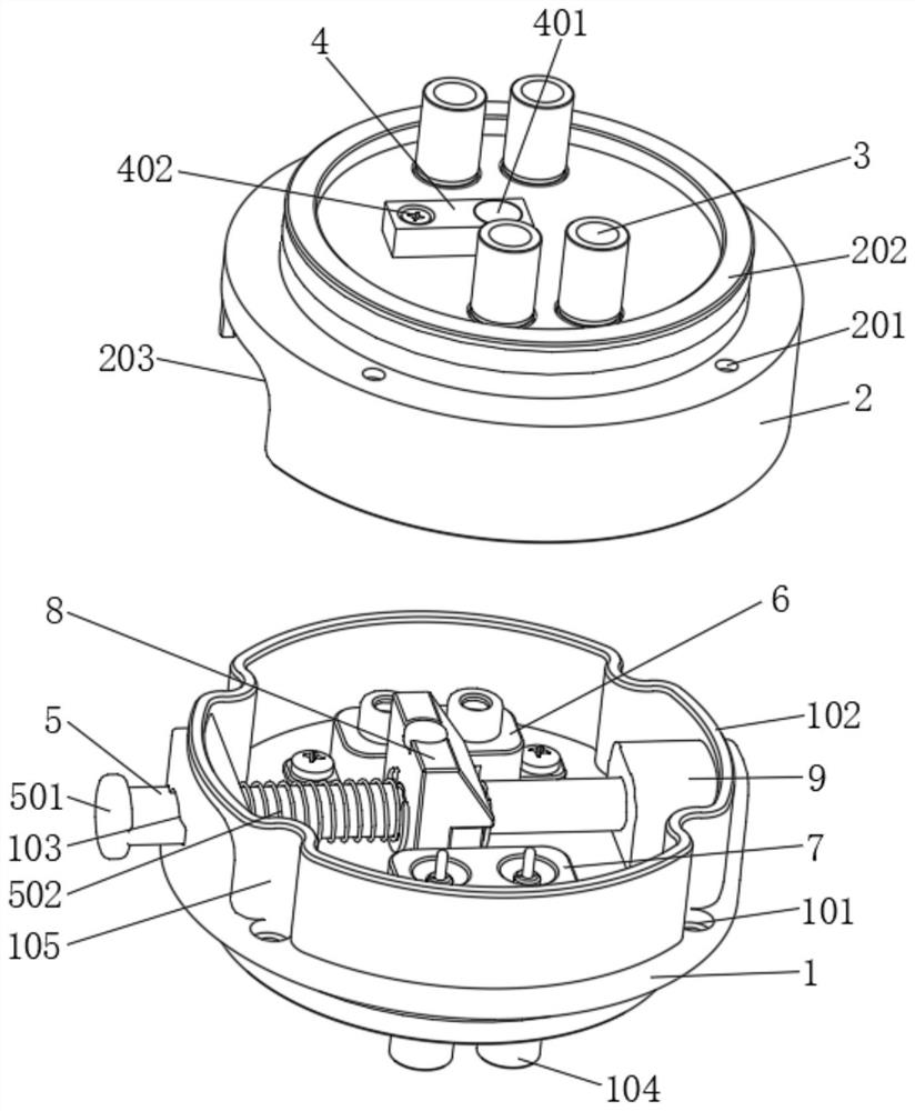
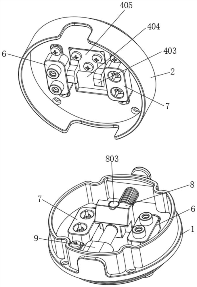
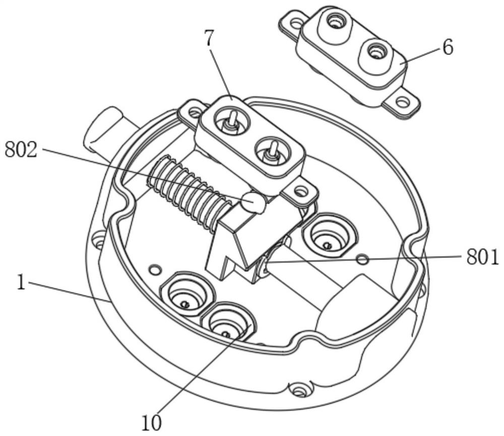
[0031] see Figure 1-6, a fast wet plug electrical connection structure, comprising a base 1, a cover shell 2 plugged into the top of the base 1, a connecting column 3 fixedly connected to the top of the cover shell 2, a magnetic induction switch 4 fixedly connected to the top of the cover shell 2, The inside of the base 1 is plugged with a plunger 5, the bottom of the plunger 5 is sleeved with a fixed block 9, and the inner bottom wall of the base 1 is provided with two quick-release head mounting seats 10, and the two quick-release head mounts 10 There are quick-release female head 6 and quick-release male head 7 respectively plugged inside. Both quick-release female head 6 and quick-release male head 7 are installed on the quick-release head mounting seat 10. Corrosion or damage may occur after long-term use , can directly replace the female head 6 of the quick release head and the male head 7 of the quick release head, which can solve the corrosion problem of the connector...
Embodiment 2
[0033] see Figure 1-4 , this embodiment provides a technical solution on the basis of Embodiment 1: a quick wet plug electrical connection structure, including a base 1, a threaded hole 101 is opened on the outside of the top of the base 1, and the top of the base 1 is fixedly connected There is a side wall 102, and a through hole 103 is opened at the position where the side wall 102 is in contact with the insertion rod 5. The bottom of the base 1 is fixedly connected with a connector 104, and the outer side of the side wall 102 is fixedly connected with a positioning block 105, and the top of the base 1 is plugged in. There is a cover shell 2, a positioning hole 201 is opened on the outside of the top of the cover shell 2, a socket 202 is fixedly connected to the top of the cover shell 2, and a positioning groove 203 is opened on the outside of the cover shell 2, through which the positioning groove 203 on the cover shell 2 and the base 1 The positioning block 105 on the top...
Embodiment 3
[0035] see Figure 1-4 , this embodiment provides a technical solution on the basis of Embodiment 1: a quick wet plug electrical connection structure, including a base 1, the top of the base 1 is plugged with a cover shell 2, and the top of the cover shell 2 is fixedly connected There is a connecting column 3, a magnetic induction switch 4 is fixedly connected to the top of the cover shell 2, a socket 401 is opened on the top of the magnetic induction switch 4, a fixing screw 402 is arranged between the magnetic induction switch 4 and the cover shell 2, and the inner top wall of the cover shell 2 The upper part is fixedly connected with a bottom plate 405 through fixing screws 402, and the bottom of the bottom plate 405 is symmetrically fixedly connected with two vertical plates 403, and a paddle 404 is rotatably connected between the two vertical plates 403, and the bottom of the magnetic induction switch 4 runs through the top of the cover shell 2 Afterwards, it is fixedly c...
PUM
 Abstract
Description
Claims
Application Information
 - R&D Engineer
- R&D Manager
- IP Professional
- Industry Leading Data Capabilities
- Powerful AI technology
- Patent DNA Extraction
Browse by: Latest US Patents, China's latest patents, Technical Efficacy Thesaurus, Application Domain, Technology Topic, Popular Technical Reports.
© 2024 PatSnap. All rights reserved.Legal|Privacy policy|Modern Slavery Act Transparency Statement|Sitemap|About US| Contact US: help@patsnap.com