Magnetic detection device and rotation detection device

A magnetic detection device and a technology for rotation detection, which are applied to measurement devices, use electromagnetic/magnetic devices to transmit sensing components, convert sensor outputs, etc., and can solve problems such as reduced signal processing accuracy.

Pending Publication Date: 2022-04-12
HIROSE ELECTRIC GROUP
View PDF1 Cites 0 Cited by
  • Summary
  • Abstract
  • Description
  • Claims
  • Application Information

AI Technical Summary

Problems solved by technology

When such a situation occurs, there is a possibility that the accuracy of the above-mentioned signal processing may decrease.

Method used


Image

  • Magnetic detection device and rotation detection device
  • Magnetic detection device and rotation detection device
  • Magnetic detection device and rotation detection device

Examples


Embodiment Construction

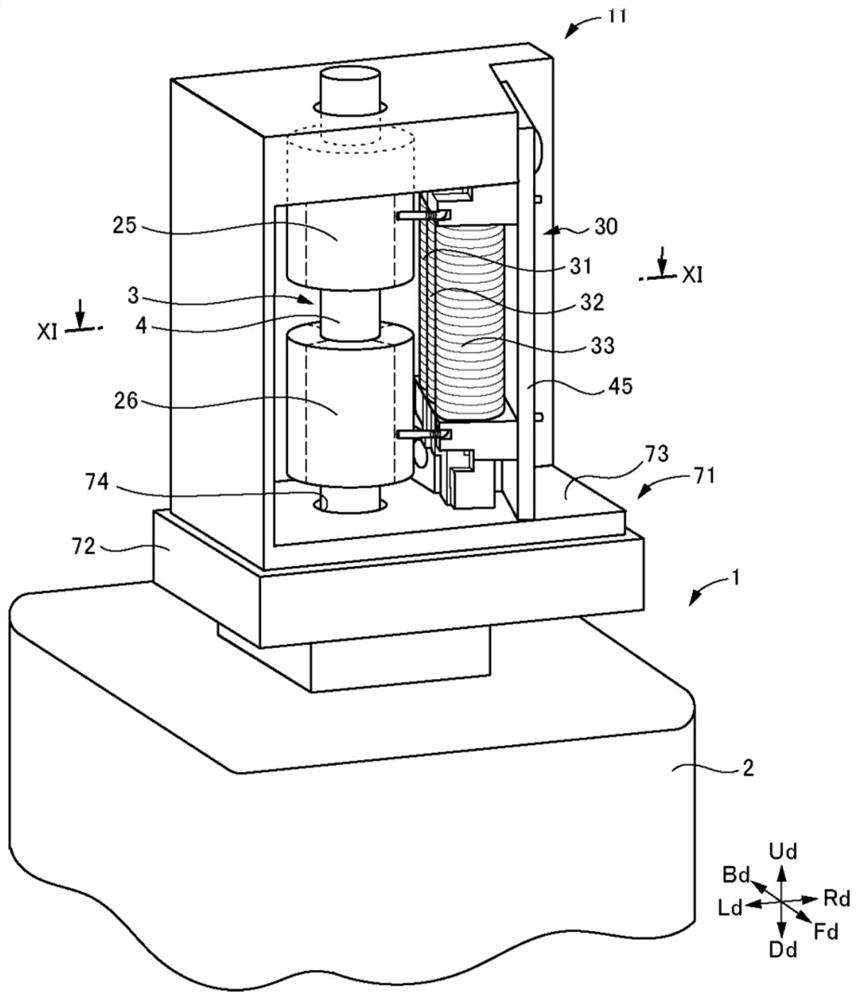
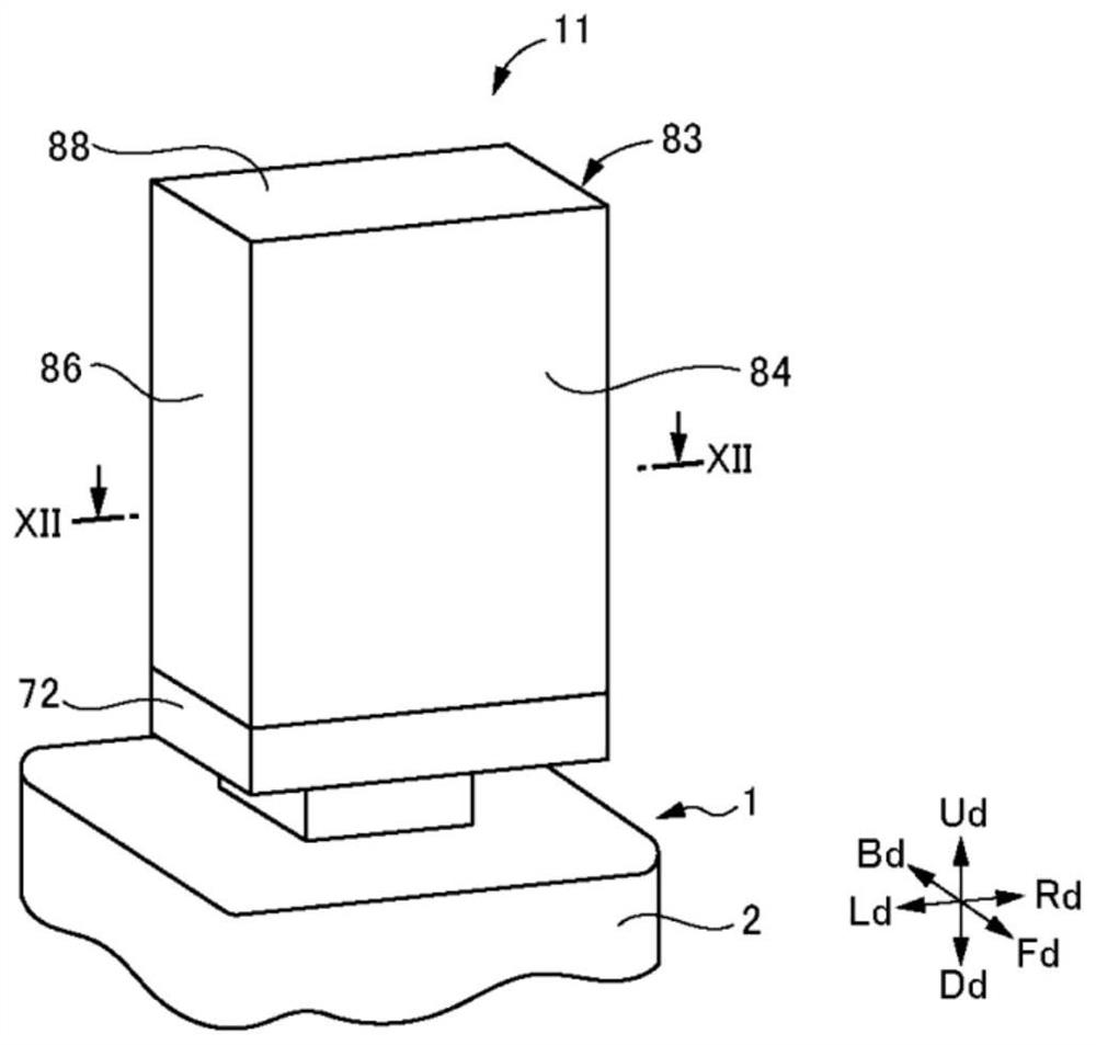
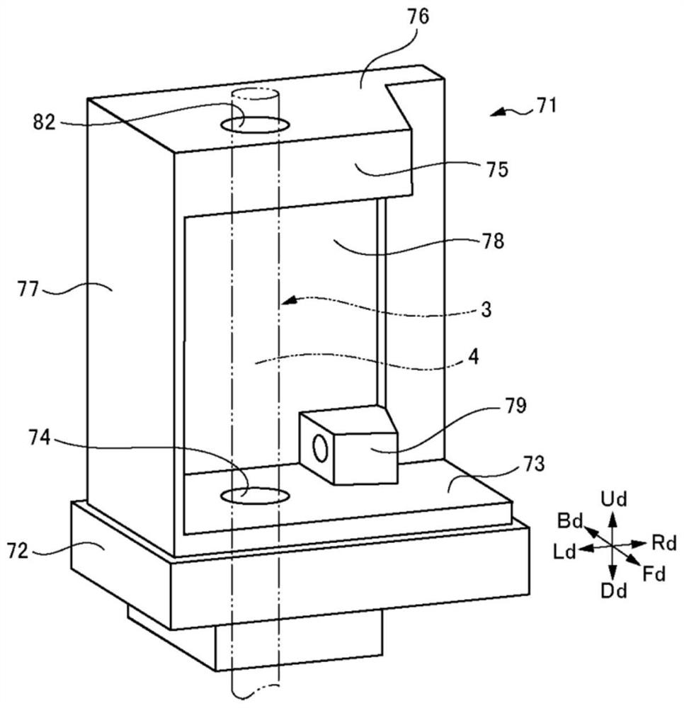
[0040] (rotation detection device)

[0041] figure 1 The rotation detection device 11 according to the embodiment of the present invention and the electric motor 1 incorporating the rotation detection device 11 are shown in a state where the housing is removed. The electric motor 1 is a specific example of a rotating device. Such as figure 1 As shown, the electric motor 1 includes a main body 2 and a rotating shaft 3 rotatably provided on the main body 2 . When the electric motor 1 is in operation, the rotary shaft 3 rotates relative to the main body 2 . In addition, one end side of the rotating shaft 3 protrudes from the main body 2 . Hereinafter, one end side portion of the rotating shaft 3 protruding from the main body 2 is referred to as a protruding portion 4 .

[0042] In addition, in the description of the embodiment, when describing the directions of up (Ud), down (Dd), front (Fd), back (Bd), left (Ld), and right (Rd), as a principle, based on figure 1 Arrows dep...


PUM

PropertyMeasurementUnit
lengthaaaaaaaaaa

Abstract

The invention relates to a magnetic detection device, which enables the distances between a magnetic wire rod and the axis of a rotating shaft to be equal to each other even if three magnetic sensors are installed on a substrate in a concentrated manner, and improves the precision of signal processing for recognizing the rotation of the rotating shaft. A magnetic detection unit (30) of a rotation detection device is provided with three magnetic sensors (31-33) and a substrate (45) on which the magnetic sensors are mounted. Each magnetic sensor is provided with a magnetic wire (34) that generates a large Barkhausen effect, a coil (35), and a bobbin (36). Each of the magnetic sensors is disposed on the substrate such that the extension direction of the magnetic wire is parallel to the substrate (45), and the magnetic detection unit is disposed on the outer peripheral side of the track of the magnetic field forming unit such that the extension direction of the magnetic wire is parallel to the axial direction of the rotating shaft (3). The positions of the magnetic wire arrangement parts (38) in the bobbins in the magnetic sensors are set so that the distances between the magnetic wires of the three magnetic sensors and the rotating shaft are equal to each other.

Description

technical field [0001] The present invention relates to a magnetic detection device and a rotation detection device for detecting rotation of a rotating shaft of a rotating device such as an electric motor using magnetism. Background technique [0002] For example, as a device that detects the rotation of a rotating shaft of a rotating device such as an electric motor, a rotation detecting device using a magnetic wire that produces the large Barkhausen effect is known. An example of such a rotation detection device is described in Patent Document 1 below. [0003] The rotation detection device described in Patent Document 1 is as described in this document figure 1 as well as figure 2 As shown, there are four magnetic field forming parts and three magnetic sensors. [0004] Permanent magnets are used as the respective magnetic field forming portions. The four magnetic field forming parts are arranged around the rotating shaft at intervals of 90 degrees. In addition, th...

Claims


Application Information

Patent Timeline
Patent Type & Authority Applications(China)
IPC IPC(8): G01D5/244
CPCG01P3/4815G01D5/145G01D5/20
Inventor 江川广祐
Owner HIROSE ELECTRIC GROUP
Why Eureka
Try Eureka