Water turbine type aircraft constant torque arresting adjusting system

An adjustment system and constant torque technology, applied in the direction of the stop device, etc., can solve the problems of reducing the service life of the aircraft, adjusting the resistance of the aircraft, and poor economy, and achieve the effects of reducing physical discomfort, reducing peak load and improving service life.

Pending Publication Date: 2022-04-12
沈阳恩义优液压技术有限公司
View PDF0 Cites 1 Cited by
  • Summary
  • Abstract
  • Description
  • Claims
  • Application Information

AI Technical Summary

Problems solved by technology

Although the arresting safety of different types of aircraft can be guaranteed by configuring multiple sets of water turbine brakes, it also leads to the disadvantages of cumbersome installation and maintenance, and poor economy
[0004] In addition, the traditional water turbine brake cannot adjust the output arresting force, resulting in a large load at the moment the aircraft is blocked, and the large load immediately decays after reaching the peak value, resulting in the deceleration of the aircraft when it is blocked. Huge, excessive deceleration acts on the aircraft fuselage, not only will reduce the service life of the aircraft, but also the pilot will cause serious physical discomfort in the environment of excessive deceleration

Method used


Image

  • Water turbine type aircraft constant torque arresting adjusting system
  • Water turbine type aircraft constant torque arresting adjusting system
  • Water turbine type aircraft constant torque arresting adjusting system

Examples


Embodiment Construction

[0016] The present invention will be further described in detail below in conjunction with the accompanying drawings and specific embodiments.

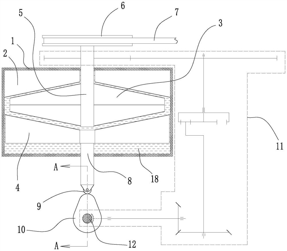
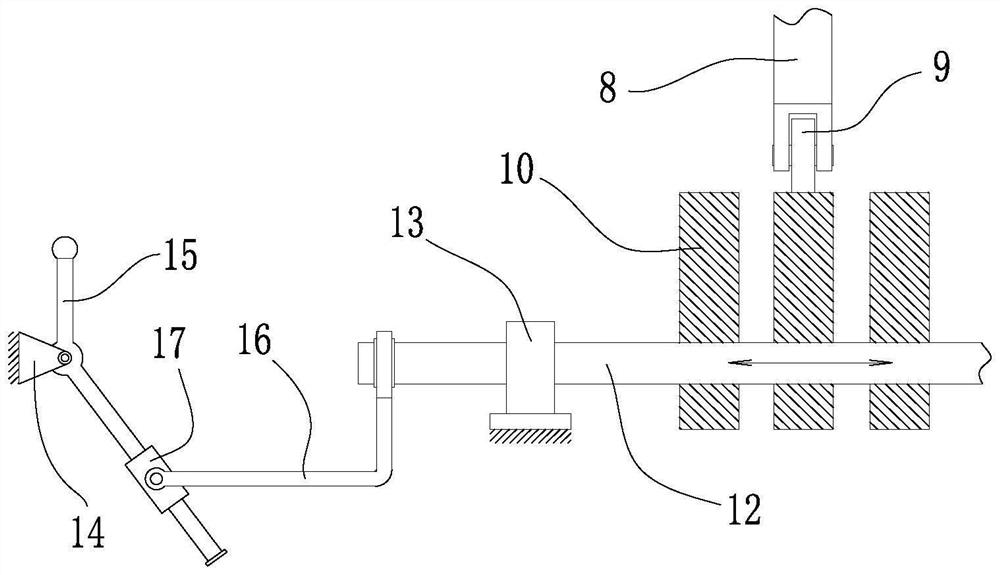
[0017] Such as figure 1 , 2 As shown, a water turbine type aircraft constant moment arresting adjustment system includes a housing 1, an upper stator 2, a rotor 3, a lower stator 4, a rotating shaft 5, a cable reel 6, an arresting belt 7, a push rod 8, a roller 9, Cam 10 and deceleration mechanism 11; the sealed space inside the housing 1 is filled with a fluid medium 18; the upper stator 2 is located inside the housing 1, and the upper stator 2 is fixedly connected to the lower surface of the top plate of the housing 1; the rotor 3 is located inside the housing 1 and below the upper stator 2, the rotating shaft 5 seals through the top plate of the housing 1 and extends to the inside of the housing 1, the rotor 3 is fixedly connected to the rotating shaft 5, and the rotating shaft 5 has a degree of freedom of rotation; The lower sta...


PUM


Abstract

A water turbine type aircraft constant-torque arresting adjusting system is characterized in that a shell is filled with a fluid medium, an upper stator, a rotor and a lower stator are located in the shell, the upper stator is fixedly connected with the shell, a rotating shaft penetrates through a top plate of the shell and is fixedly connected with the rotor, a push rod penetrates through a bottom plate of the shell and is fixedly connected with the lower stator, and a rope belt disc wound with an arresting belt is fixedly arranged at the top of the rotating shaft; the cams are located below the push rod and make contact with the push rod through rollers, the cams are arranged on the cam shaft and can change positions so as to achieve multiple purposes, and the rotating shaft is in transmission connection with the cam shaft through a speed reducing mechanism. After an aircraft lands, the arresting belt stops and drives the rotor to rotate, inertia kinetic energy of the aircraft is consumed under the damping action of a fluid medium, meanwhile, the cam is driven to rotate through the speed reducing mechanism, the axial gap distance between the stator and the rotor is changed through movement of the push rod, then the arresting force is changed, and the peak load of the aircraft when the aircraft is arresting is effectively reduced. Meanwhile, the deceleration of the aircraft during arresting is reduced, the service life of the aircraft is prolonged, and the body discomfort of a pilot is reduced.

Description

technical field [0001] The invention belongs to the technical field of aircraft arresting, in particular to a water turbine type aircraft constant moment arresting adjustment system. Background technique [0002] At present, the arresting system used by aircraft is mainly water turbine brakes. The traditional water turbine brakes belong to the "one machine, one use" type, that is, they are customized according to the specific model parameters of the aircraft. If the water turbine brake is customized for light aircraft, then the water turbine brake cannot meet the arresting requirements of heavy aircraft. If it is used for arresting heavy aircraft, the arresting distance of heavy aircraft may exceed the set limit value, resulting in The heavy aircraft overshot the runway and was damaged. If the water turbine brake is custom-made for heavy aircraft, then the water turbine brake cannot meet the arresting needs of light aircraft. damaged by overloading. [0003] Therefore, in...

Claims


Application Information

Patent Timeline
Patent Type & Authority Applications(China)
IPC IPC(8): B64F1/02
Inventor 宋锦春刘士琦柴昕武
Owner 沈阳恩义优液压技术有限公司
Why Eureka
Try Eureka