Light aluminum alloy floor processing equipment and processing method
A processing equipment, aluminum alloy technology, applied in metal processing equipment, metal processing mechanical parts, shearing machine equipment and other directions, can solve the problems of inconvenience in actual use, inconvenience in adjusting the shearing knife, inconvenient in adjusting the cutting position of the shearing knife, etc. achieve the effect of avoiding rotation
- Summary
- Abstract
- Description
- Claims
- Application Information
AI Technical Summary
Problems solved by technology
Method used
Image
Examples
Embodiment 1
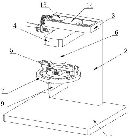
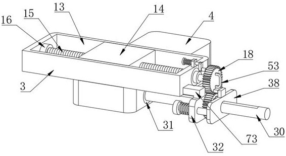
[0039] Embodiment one, by Figure 1 to Figure 8 Provided, the present invention includes an operating table 1, the top of the operating table 1 is fixedly connected with a supporting side plate 2, one side of the supporting side plate 2 is fixedly connected with a first fixed plate 3, and the bottom of the first fixed plate 3 is provided with a movable seat 4. An installation seat 5 is provided under the movable seat 4, and a hydraulic telescopic cylinder 6 is provided on the top of the installation seat 5. The hydraulic telescopic cylinder 6 and the movable seat 4 are connected through a shear adjustment assembly, and a turntable 7 is provided under the installation seat 5. The bottom of the turntable 7 is provided with a knife seat 8, the bottom of the knife seat 8 is fixedly connected with a shear knife 9, the top of the turntable 7 is provided with a first annular groove 10, and a first sliding ring 11 is arranged in the first annular groove 10. , the first sliding ring 11...
Embodiment 2
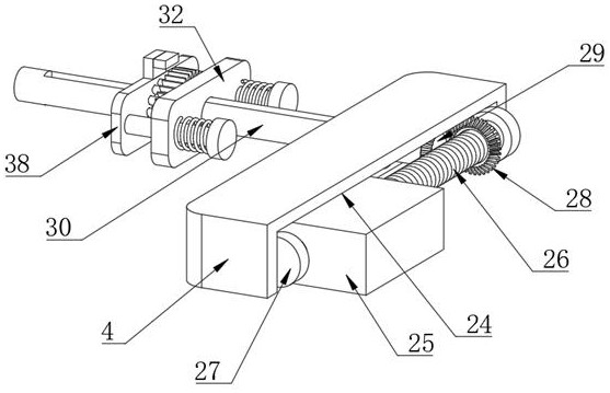
[0041] Embodiment two, on the basis of embodiment one, by figure 1 , figure 2 , image 3 , Figure 4 and Figure 5Given, the shear adjustment assembly includes a first chute 24 opened at the bottom of the movable seat 4, a second slide block 25 is arranged in the first chute 24, and the bottom of the second slide block 25 is fixed to the top of the hydraulic telescopic cylinder 6 Connection, the first chute 24 is provided with a second threaded column 26, the second threaded column 26 runs through the second slider 25, the connection mode of the second threaded column 26 and the second slider 25 is threaded connection, the second threaded column 26 both ends are all connected with the inner wall of the first chute 24 by the 3rd bearing 27, the first chute 24 is provided with the first bevel gear 28, the second threaded column 26 runs through the first bevel gear 28, and the second A bevel gear 28 is fixedly connected with the second threaded post 26, and one side of the f...
Embodiment 3
[0043] Embodiment three, on the basis of embodiment one, by Figure 6 and Figure 7 Given, the anti-rotation fixing assembly includes a number of limit grooves 65 opened on the top of the turntable 7, two second movable plates 54 are provided on the top of the mounting seat 5, and a groove 55 is provided on one side of the second movable plate 54, and the concave A slide plate 56 is arranged in the groove 55, and one side of the slide plate 56 is fixedly connected with a third connecting plate 57, and the bottom of the third connecting plate 57 is fixedly connected with a limit post 58, and the bottom of the second movable plate 54 is fixedly connected with two fourth connecting plates. Connecting column 60, the fourth connecting column 60 runs through the mounting seat 5, the bottom of the fourth connecting column 60 is fixedly connected with the third fixed plate 61, the outside of the fourth connecting column 60 is provided with a compression spring 62, and the two ends of ...
PUM
 Abstract
Description
Claims
Application Information
 - Generate Ideas
- Intellectual Property
- Life Sciences
- Materials
- Tech Scout
- Unparalleled Data Quality
- Higher Quality Content
- 60% Fewer Hallucinations
Browse by: Latest US Patents, China's latest patents, Technical Efficacy Thesaurus, Application Domain, Technology Topic, Popular Technical Reports.
© 2025 PatSnap. All rights reserved.Legal|Privacy policy|Modern Slavery Act Transparency Statement|Sitemap|About US| Contact US: help@patsnap.com


