Coulter mixer

A mixer and coulter technology, applied to mixers, mixers with rotating containers, mixer accessories, etc., can solve the problems of increased manual cleaning, dead material, and difficulty in discharging materials, so as to facilitate maintenance and management and improve use Longevity and easy operation

Pending Publication Date: 2022-04-12
良盛机械(湖州)有限公司
View PDF0 Cites 0 Cited by
  • Summary
  • Abstract
  • Description
  • Claims
  • Application Information

AI Technical Summary

Problems solved by technology

Due to the processing method and technical limitations of the outer shell, it is not a standard cylindrical shell and has a certain degree of out-of-roundness. The stirring blade rotates around the axis to form a standard cylinder. In order to ensure the mixing effect, the distance between the cylinder formed by the stirring shaft and the cylinder is at the lower part. Recently, leave a gap of 5mm~10mm, and the gap in other directions depends on the roundness of the shell. Poor roundness will lead to too large a gap, and some materials cannot be stirred by the stirring paddle, forming dead materials, which will affect the mixing effect.
[0003] At the same time, the discharge port is generally set in the middle of the shell, and the rotating stirring paddle cannot completely push the material to the middle of the shell, resulting in difficulty in discharging; at the same time, after the stirring is completed, there will be material residue near the two ends of the mixing barrel, which is difficult to clean. Need to increase manual cleaning, the cleaning efficiency is low, if the cleaning is not clean, it will affect the quality of subsequent mixed products; therefore, it is necessary to develop a new type of coulter mixer to solve the current problems

Method used


Image

  • Coulter mixer
  • Coulter mixer
  • Coulter mixer

Examples


Embodiment Construction

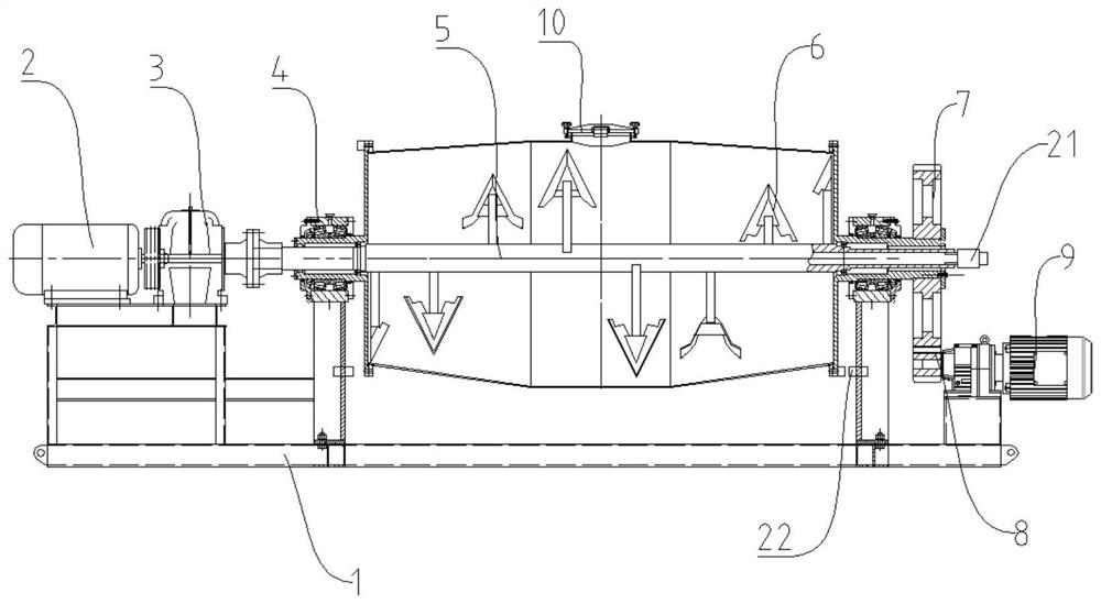
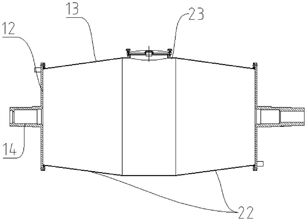
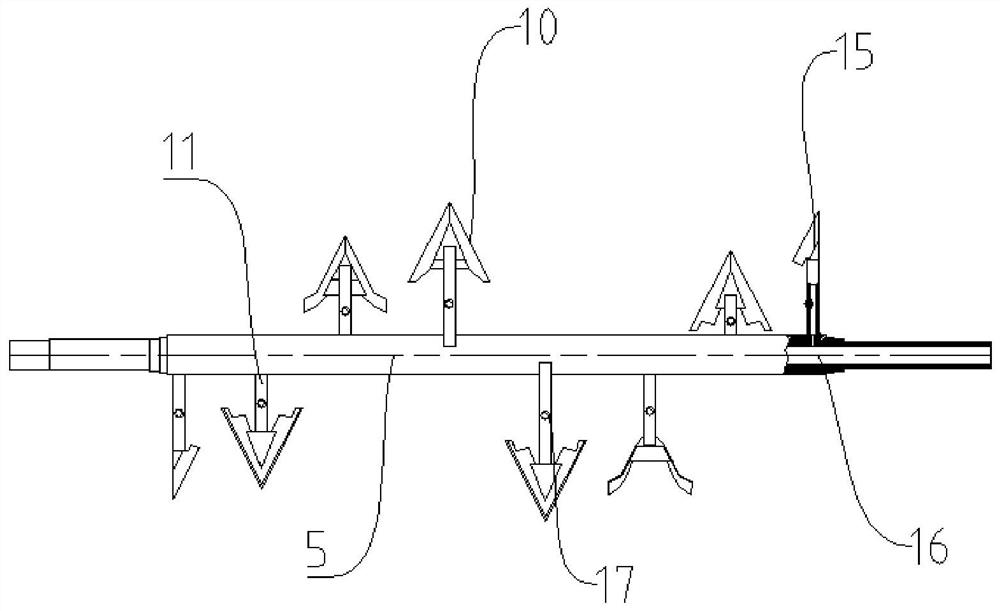
[0032] refer to Figure 1 to Figure 6 A kind of coulter mixer shown, comprises frame 1, stirring paddle motor 2, speed reducer 3, mixing tank and housing motor 9, and stirring paddle motor 2, speed reducer 3, mixing tank and housing motor 9 are fixed on On the frame 1, the stirring paddle motor 2 is connected with the speed reducer 3, the speed reducer 3 is connected with the stirring shaft 5, the stirring shaft 5 passes through the middle of the mixing barrel transversely, and the stirring shaft 5 is equipped with a stirring Paddle, stirring paddle comprises paddle 6 and paddle handle 11, and paddle 6 is fixed on the paddle handle 11, and paddle handle 11 is connected with stirring shaft 5, and described mixing bucket comprises end cover 12 and housing 13, and end cover 12 is two First, the end caps 12 are arranged at both ends of the housing 13, and the housing 13 gradually shrinks from the middle to both ends and forms a folded structure, and the middle of the housing 13 is...


PUM


Abstract

The invention discloses a coulter mixer which comprises a rack, a stirring paddle motor, a speed reducer, a stirring barrel and a shell motor, the stirring paddle motor, the speed reducer, the stirring barrel and the shell motor are fixed on the rack, the stirring paddle motor is connected with the speed reducer, the speed reducer is connected with a stirring shaft, the stirring shaft transversely penetrates through the middle of the stirring barrel, and the shell motor is connected with the stirring shaft. The stirring shaft is provided with a stirring paddle, the stirring paddle comprises a paddle blade and a paddle handle, the paddle blade is fixed on the paddle handle, and the paddle handle is connected with the stirring shaft; the stirring device is convenient to use and easy to operate, synchronous or separated rotation of the stirring shaft and the stirring barrel is achieved by arranging the stirring paddle motor and the shell motor and independently controlling the stirring shaft and the stirring barrel, automatic discharging is achieved, meanwhile, automatic cleaning operation of the interior of the stirring barrel can be completed, and cleanliness of the interior of the stirring barrel is guaranteed.

Description

technical field [0001] The invention relates to a coulter mixer. Background technique [0002] The cylinder casing of the existing coulter type mixer is fixed, the stirring shaft is placed horizontally, and the stirring shaft rotates when mixing materials. Due to the processing method and technical limitations of the outer shell, it is not a standard cylindrical shell and has a certain degree of out-of-roundness. The stirring blade rotates around the axis to form a standard cylinder. In order to ensure the mixing effect, the distance between the cylinder formed by the stirring shaft and the cylinder is at the lower part. Recently, a gap of 5 mm to 10 mm is left, and the gap in other directions depends on the roundness of the shell. Poor roundness will cause the gap to be too large, and some materials cannot be stirred by the stirring paddle, forming dead material, which affects the mixing effect. [0003] At the same time, the discharge port is generally set in the middle o...

Claims


Application Information

Patent Timeline
Patent Type & Authority Applications(China)
IPC IPC(8): B01F29/64B01F35/11B01F35/75
Inventor 周清岭林军
Owner 良盛机械(湖州)有限公司
Why Eureka
Try Eureka