
Device and method for automatically correcting position of surgical robot

A surgical robot and automatic calibration technology, applied in surgical robots, surgical navigation systems, etc., can solve problems such as robot calibration deviation, unfavorable direct observation, and impact on calibration accuracy, so as to solve positioning deviation, reduce weight and structural complexity, and reduce The effect of occlusion

Active Publication Date: 2022-04-12
ZHUHAI WEIERKANG BIOTECH
View PDF7 Cites 2 Cited by
  • Summary
  • Abstract
  • Description
  • Claims
  • Application Information

AI Technical Summary

Problems solved by technology

[0002] In recent years, surgical operations tend to be minimally invasive. While bringing convenience such as small wounds, less blood loss, and faster recovery, it also narrows the doctor's field of vision, which is not conducive to direct observation. Surgical robots are generally used to assist surgery. Before the operation, MRI, CT and other medical image data are used to reconstruct the 3D model, and then the surgical auxiliary robot is used for navigation. However, when the existing surgical auxiliary robot is calibrated, the navigation target at the working end is used as the positioning coordinates, and the coordinates of the robot body are not used as the surgical coordinates. Navigation and positioning coordinates in the middle, and the surgical robot moves to other surgical environments, which will affect the initial calibration accuracy. At the same time, due to the uneven ground or table top of the complex scene, it will also cause the robot to correct the deviation and affect the accuracy during use. The final output The result is wrong. Therefore, it is particularly important to use a surgical robot that uses itself as a benchmark, has automatic position correction, and can maintain accurate correction in a variety of complex environments.

Method used


Image

  • Device and method for automatically correcting position of surgical robot
  • Device and method for automatically correcting position of surgical robot
  • Device and method for automatically correcting position of surgical robot

Examples


Embodiment Construction

[0028] The following will clearly and completely describe the technical solutions in the embodiments of the present invention with reference to the accompanying drawings in the embodiments of the present invention. Obviously, the described embodiments are only some, not all, embodiments of the present invention. Based on the embodiments of the present invention, all other embodiments obtained by persons of ordinary skill in the art without making creative efforts belong to the protection scope of the present invention.

[0029] In the description of the present invention, it should be noted that the terms "center", "upper", "lower", "left", "right", "vertical", "horizontal", "inner", "outer" etc. The indicated orientation or positional relationship is based on the orientation or positional relationship shown in the drawings, and is only for the convenience of describing the present invention and simplifying the description, rather than indicating or implying that the referred d...


PUM


Abstract

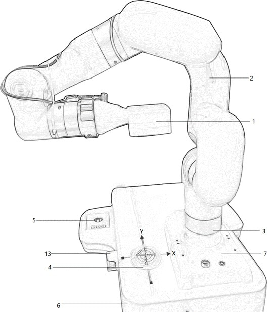
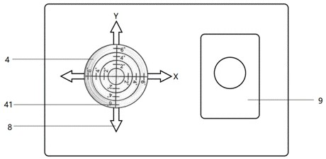
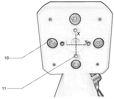
The invention discloses an automatic position correction device and method for a surgical robot. The automatic position correction device comprises a base, an XY-axis bubble level is arranged on the upper surface of the base, a base bayonet is formed in one side of the XY-axis bubble level, a mounting seat is fixedly connected to the base bayonet, a base is movably connected to the mounting seat, the base is connected with a mechanical arm, and the other end of the mechanical arm is connected with a working end. The lower surface of the working end is provided with four laser indicating lamps, the four laser indicating lamps are arranged in a cross shape, and the periphery of the four laser indicating lamps is provided with a plurality of three-dimensional panoramic visual lenses. And a unified coordinate system is quickly established, so that the purpose of more accurate operation positioning is achieved.

Description

technical field [0001] The invention relates to the technical field of tool coordinate correction, in particular to an automatic position correction device and method for a surgical robot. Background technique [0002] In recent years, surgical operations tend to be minimally invasive. While bringing convenience such as small wounds, less blood loss, and faster recovery, it also narrows the doctor's field of vision, which is not conducive to direct observation. Surgical robots are generally used to assist surgery. Before the operation, MRI, CT and other medical image data are used to reconstruct the 3D model, and then the surgical auxiliary robot is used for navigation. However, when the existing surgical auxiliary robot is calibrated, the navigation target at the working end is used as the positioning coordinates, and the coordinates of the robot body are not used as the surgical coordinates. Navigation and positioning coordinates in the middle, and the surgical robot moves...

Claims


Application Information

Patent Timeline
Patent Type & Authority Applications(China)
IPC IPC(8): A61B34/30A61B34/20
Inventor 胡善云
Owner ZHUHAI WEIERKANG BIOTECH
Learn More