3D building printing leveling device and 3D building printing equipment

A leveling and building technology, applied in construction, building structure, processing of building materials, etc., can solve problems such as reducing the leveling efficiency, increasing the number of steps in the leveling process, and the surface of the scraper being no longer flat.

Pending Publication Date: 2022-04-08
建筑材料工业技术监督研究中心 +1
View PDF0 Cites 0 Cited by
  • Summary
  • Abstract
  • Description
  • Claims
  • Application Information

AI Technical Summary

Problems solved by technology

However, since the concrete paste has not yet completely solidified when troweling is performed, a small amount of concrete paste will stick to the scraper
After multiple troweling, these bonded concrete will cause the surface of the scraper to be no longer smooth, and continuing to use such a scraper for troweling will cause marks on the concrete surface, which will seriously affect the troweling effect
[0006] However, if the scraper is cleaned, the steps of the smoothing process will increase, which will not only greatly reduce the smoothing efficiency, but also affect the overall quality of the concrete wall.

Method used


Image

  • 3D building printing leveling device and 3D building printing equipment
  • 3D building printing leveling device and 3D building printing equipment
  • 3D building printing leveling device and 3D building printing equipment

Examples


Embodiment 1

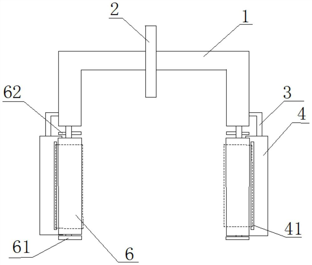
[0062] Such as figure 1 As shown, in this embodiment, the side of the smoothing drive belt 5 facing the inside of the frame 1 is located on the same vertical plane as the corresponding inner surface of the side wall of the frame 1 .

Embodiment 2

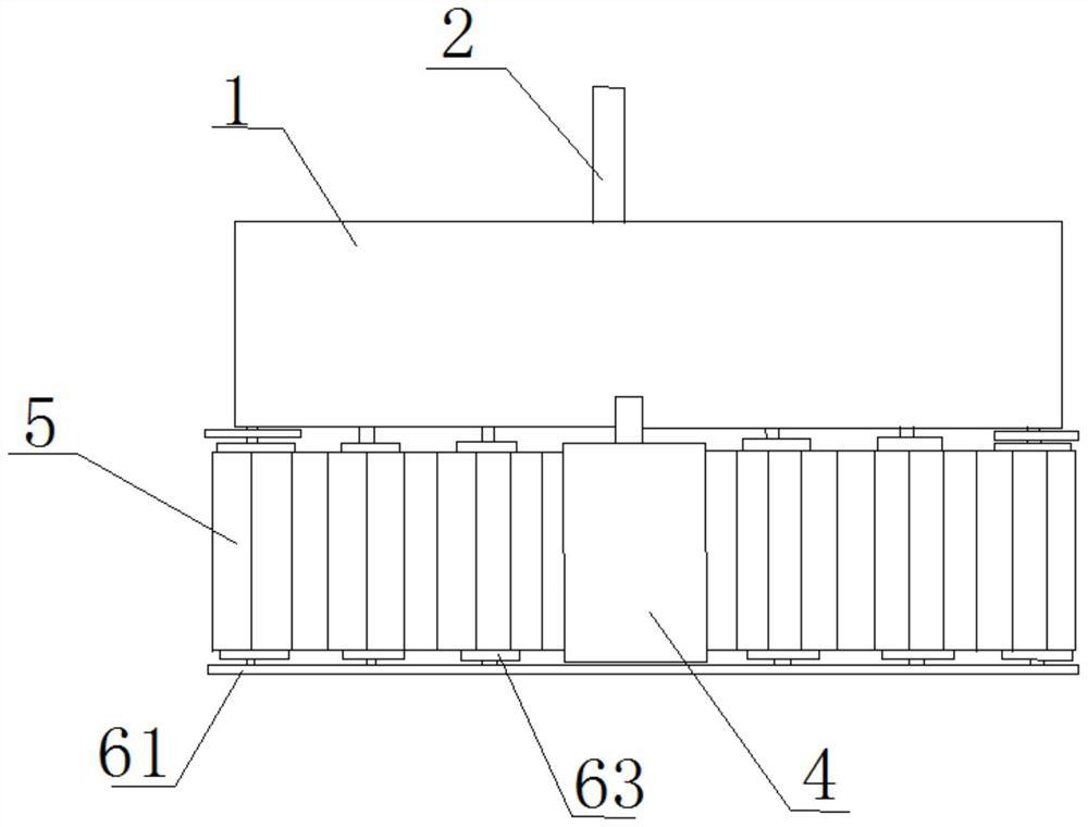
[0064] Such as Figure 4 As shown, in this embodiment, two smoothing transmission belts 5 are located on both sides outside the frame 1 . In this embodiment, the upper ends of the roller shafts of the two vertical rollers 6 in each leveling assembly are fixed on the connecting rod 3 on the same side.

[0065] In this embodiment, the connecting rod 3 is a telescopic rod that can be stretched and positioned in the horizontal direction, so that the distance between the two flat transmission belts 5 can be adjusted, so that the device of this embodiment has a wider range of applications.

Embodiment 3

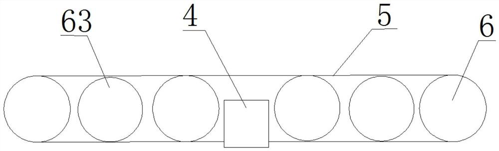
[0067] Such as Figure 5 As shown, in this embodiment, two flat driving belts 5 are located on both sides inside the frame 1 . In the present embodiment, the upper ends of the roller shafts of the two vertical rollers 6 in each leveling assembly are fixed to the lower end of the side wall of the frame 1, and the retarded liquid storage tank 4 is also fixed to the lower end of the side wall of the frame 1; A flat transmission belt 5 is arranged in the frame 1, which is beneficial to reduce the volume of the device.

[0068] In the process of printing and smoothing, since the two leveling transmission belts 5 of the present embodiment are located in the frame 1, the sprayed concrete slurry is easy to spray to the upper sides of the leveling transmission belts 5 on both sides, which is easy to vertical The rotation of the roller 6 and the rotation of the leveling drive belt 5 have an effect.

[0069] Therefore, in this embodiment, there are also two deflectors 11 arranged obliq...


PUM


Abstract

The invention relates to a 3D building printing technology, in particular to a 3D building printing leveling device and 3D building printing equipment. A frame of the device is hollow, the two opposite sides and the lower side of the frame are open, and the frame can move in the direction where the openings in the two sides are located. A sprayer is fixedly mounted on the upper side of the frame and sprays towards the interior of the frame; a leveling assembly is arranged below each of two opposite end side walls of the frame; each leveling assembly comprises two vertical rollers arranged in the horizontal direction, a leveling transmission belt and a delayed coagulation liquid storage tank, and the two vertical rollers are rotationally installed on the frame; the two vertical rollers are sleeved with the flattening transmission belt. The delayed coagulation liquid storage tank is located between the two vertical rollers and fixed to the frame, and the side, facing the outside of the frame, of the flat transmission belt penetrates through the delayed coagulation liquid storage tank. According to the device, retarding liquid can be attached to the surface of the leveling transmission belt, and concrete slurry is prevented from being bonded to the leveling transmission belt; the device is high in operation efficiency and good in leveling effect.

Description

technical field [0001] The invention relates to 3D building printing technology, in particular to a 3D building printing leveling device and 3D building printing equipment. Background technique [0002] At present, in the field of construction, 3D printing technology has gradually received widespread attention. [0003] In the process of 3D architectural printing, smoothing or leveling the surface of the printed concrete structure is an important technology that determines the efficiency and quality of the 3D architectural printing process. [0004] In the prior art, the main concern of people is how to smooth the marks between two adjacent layers of concrete. However, for 3D architectural printing, the leveling of each layer of concrete itself cannot be ignored. [0005] In the prior art, the main component for smoothing and smoothing is the scraper. However, since the concrete paste is not completely solidified when troweling is performed, a small amount of concrete pas...

Claims


Application Information

Patent Timeline
IPC IPC(8): E04G21/04E04G21/10B33Y30/00B33Y40/20
Inventor 齐冬有汪智勇何昌毓张钰王建黔李长虹马旺坤王晓鹏
Owner 建筑材料工业技术监督研究中心
Why Eureka
Try Eureka