
Anti-blocking pump valve pipeline with garbage collection function

A garbage collection and anti-clogging technology, applied in the direction of pipe components, pipes/pipe joints/fittings, grain processing, etc., can solve the problems of no better dredging, no garbage collection and treatment, etc.

Pending Publication Date: 2022-04-08
范富玲
View PDF7 Cites 0 Cited by
  • Summary
  • Abstract
  • Description
  • Claims
  • Application Information

AI Technical Summary

Problems solved by technology

[0003] The purpose of the present invention is to solve the shortcomings of the existing pump valve pipeline, which has no better dredging effect and no function of collecting and processing garbage, and proposes an anti-clogging pump valve pipeline with garbage collection function

Method used


Image

  • Anti-blocking pump valve pipeline with garbage collection function
  • Anti-blocking pump valve pipeline with garbage collection function
  • Anti-blocking pump valve pipeline with garbage collection function

Examples


Embodiment 1

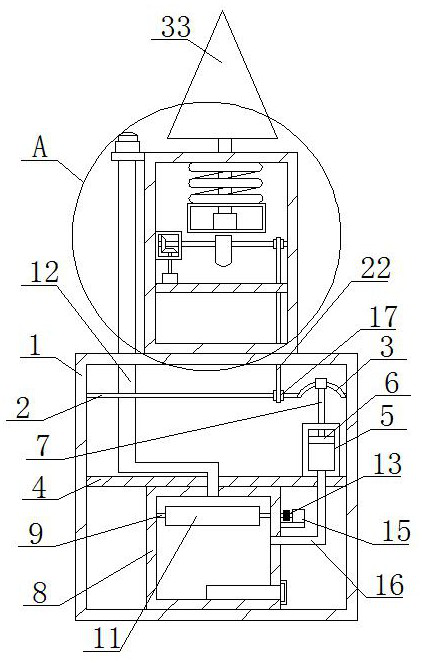
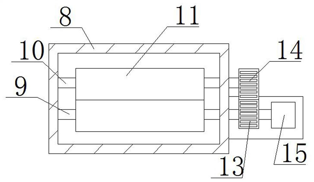
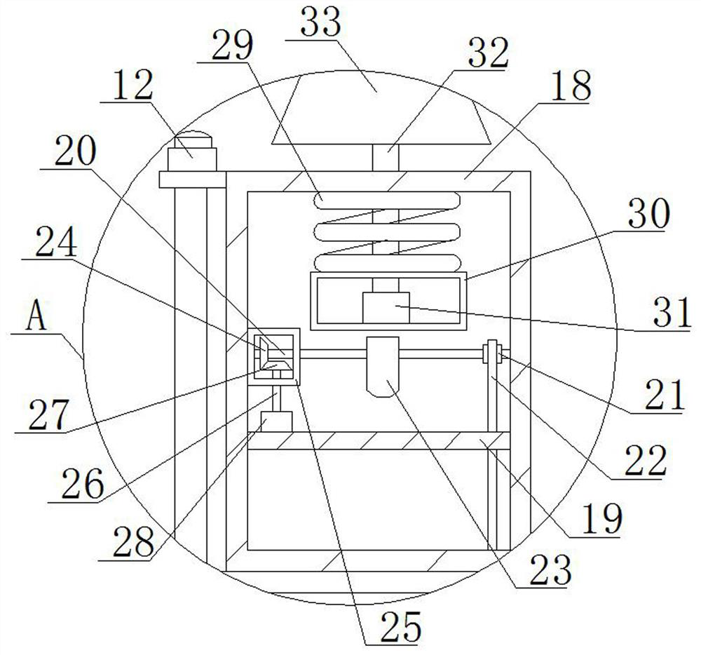
[0028] refer to Figure 1-5 , an anti-clogging pump valve pipeline with garbage collection function, comprising a processing box 1, a first rotating rod 2 is rotatably connected in the processing box 1, an arched rod 3 is fixedly connected to one end of the first rotating rod 2, and the processing box 1 A first partition 4 is fixedly installed inside, a vacuum seat 5 is fixedly installed on the first partition 4, a piston plate 6 is arranged inside the vacuum seat 5, a long rod 7 is fixedly connected to the piston plate 6, and the long rod 7 is connected with the arched Rod 3 is movably connected, and the bottom of the first dividing plate 4 is fixedly installed with collecting box 8, and the first rotating column 9 and the second rotating column 10 are rotatably connected in collecting box 8, on the first rotating column 9 and the second rotating column 10 Both are fixedly connected with a crushing column 11, and one end of the first rotating column 9 and the second rotating ...

Embodiment 2

[0039] refer to Figure 1-5, an anti-clogging pump valve pipeline with garbage collection function, comprising a processing box 1, a first rotating rod 2 is rotatably connected in the processing box 1, an arched rod 3 is welded and connected to one end of the first rotating rod 2, and the processing box 1 The first partition 4 is welded and installed inside, and the vacuum seat 5 is welded and installed on the first partition 4. The vacuum seat 5 is provided with a piston plate 6, and a long rod 7 is welded on the piston plate 6, and the long rod 7 is connected with the arch. Rod 3 is movably connected, and the bottom of first dividing plate 4 is welded with collecting box 8, and the first rotating column 9 and the second rotating column 10 are rotatably connected in collecting box 8, on the first rotating column 9 and the second rotating column 10 All are welded and connected with a crushing column 11, and one end of the first rotating column 9 and the second rotating column ...


PUM


Abstract

The invention belongs to the technical field of pipeline blockage dredging, particularly relates to an anti-blockage pump valve pipeline with a garbage collection function, and aims at solving the problems that an existing pump valve pipeline does not have a better dredging effect and does not have a garbage collection treatment function. A first rotating rod is rotationally connected into the treatment box, one end of the first rotating rod is fixedly connected with an arch-shaped rod, a first partition plate is fixedly installed in the treatment box, a vacuum seat is fixedly installed on the first partition plate, a piston plate is arranged in the vacuum seat, a long rod is fixedly connected to the piston plate, and the long rod is movably connected with the arch-shaped rod. A collecting box is fixedly mounted at the bottom of the first partition plate, a first rotating column and a second rotating column are rotationally connected to the interior of the collecting box, and smashing columns are fixedly connected to the first rotating column and the second rotating column correspondingly. The device is simple in structure, the dredging effect is better achieved, garbage is collected and smashed, and people can use the device conveniently.

Description

technical field [0001] The invention relates to the technical field of unclogging pipeline blockages, in particular to an anti-clogging pump valve pipeline with a garbage collection function. Background technique [0002] The pump valve pipeline is mainly used for liquid transportation. When the liquid is transported, a large amount of debris will be deposited in the drainage pipeline, which will cause the drainage pipeline to block, resulting in a decrease in the delivery efficiency of the drainage pipeline to the liquid. When the pump valve pipeline drains the sewage, usually People use pillars to directly push out the clogged garbage. In the application number: 201911398188.9, the invention provides an anti-clogging pump valve pipeline with garbage collection function. The pump valve pipeline with anti-clogging function includes a drill bit, a first connecting sleeve 1. The second connecting sleeve and the water inlet pipe, the drill bit is connected to the first connecti...

Claims


Application Information

Patent Timeline
Patent Type & Authority Applications(China)
IPC IPC(8): B02C4/02F16L55/24
Inventor 范富玲
Owner 范富玲
Learn More