Cable length metering device in tunnel construction
A cable length, measuring device technology, applied in the direction of measuring devices, testing dielectric strength, instruments, etc., can solve the problems of complex equipment, difficult cable length measurement, etc., to achieve the effect of simple structure
- Summary
- Abstract
- Description
- Claims
- Application Information
AI Technical Summary
Problems solved by technology
Method used
Image

Examples
Embodiment 1
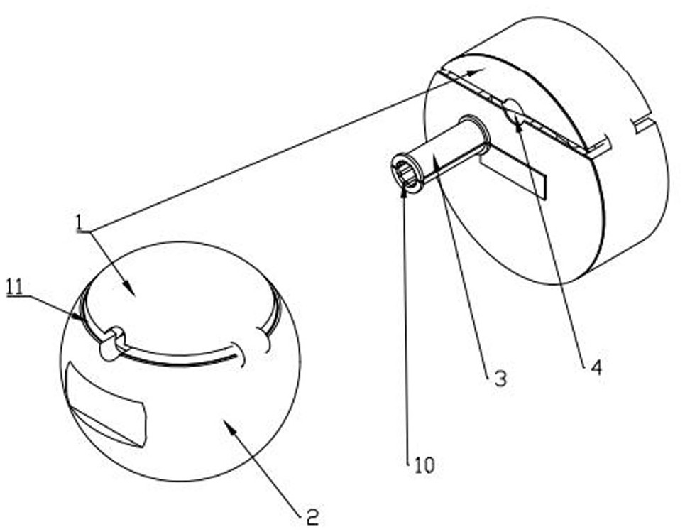
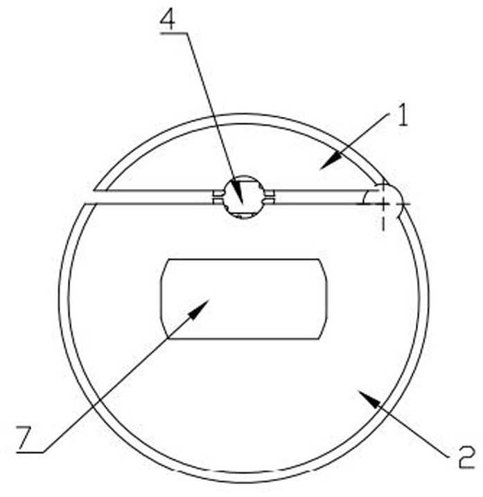
[0039] A cable length measuring device in tunnel construction, see Figure 1 to Figure 9 , including at least one spherical or cylindrical shell, the shell includes an upper cover 1 and a lower seat 2 that are hingedly connected, the center position of the upper cover 1 and the lower seat 2 is provided with a cable through hole 4, and the upper cover 1 is provided with There is a top pressure roller 5 tangential to the cable, and a bottom top roller 6 is arranged inside the lower seat 2, and the bottom top roller 6 is connected to a meter counter for recording its rotational speed; the size of the cable through hole 4 is larger than the outer surface of the tested cable. Diameter; at least one of the top pressure roller 5 or the bottom top roller 6 is an anti-drum shape with an outer diameter increasing from the center to both sides to realize the cable limit; the shell is provided with anti-slip lines and a display screen 7, and the display screen 7 is connected to the control...
Embodiment 2
[0044] The principle of this embodiment is the same as that of Embodiment 1, the specific difference is that the light strip is replaced by a light strip installed in the upper cover 1 , and a light-transmitting slit is provided in the shape and size between the upper cover 1 and the lower cover. This design can be used as a signal light ball in the tunnel environment with poor lighting conditions. Its light source power is low, but it can guide the staff. One is to indicate the position of the cable to prevent bumping, and the other is to mark the cable itself for convenience Handover of work information during shifts between teams.
Embodiment 3
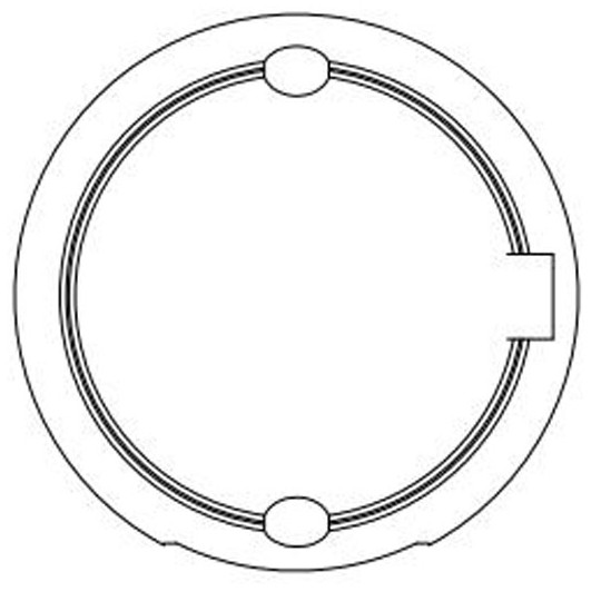
[0046] The principle of this embodiment is the same as that of Embodiment 1, and the specific difference is that an electric pen original 17 is respectively provided before and after the cable through hole 4 of the lower base 2, and the electric pen original 17 is in the shape of an open fish mouth as a whole. Fixed on the lower seat 2, the upper part 14 and the lower part 15 are fixed to form an annular ring through a hinged connection, and an annular wire 16 forming a circumference is arranged in the annular ring, and an electric pen circuit is arranged on the upper part 14, and the electric pen circuit and the annular wire 16 phase connections.
[0047] The outer surfaces of the top pressure roller 5 and the bottom top roller 6 are attached with a water-absorbing layer, and the central axes of the top pressure roller 5 and the bottom pressure roller are made of insulating materials. The electric pen is externally connected to the flexible signal rod 18 suspended in the air,...
PUM
 Abstract
Description
Claims
Application Information
 - R&D
- Intellectual Property
- Life Sciences
- Materials
- Tech Scout
- Unparalleled Data Quality
- Higher Quality Content
- 60% Fewer Hallucinations
Browse by: Latest US Patents, China's latest patents, Technical Efficacy Thesaurus, Application Domain, Technology Topic, Popular Technical Reports.
© 2025 PatSnap. All rights reserved.Legal|Privacy policy|Modern Slavery Act Transparency Statement|Sitemap|About US| Contact US: help@patsnap.com