High-strength low-cost stable rotating brake parachute
A stable rotation, low-cost technology, applied in the field of speed parachute, can solve the problems of low strength, overall mess, and inability to effectively limit the pull rope, etc., and achieve the effect of firm and stable pulling strength, not easy to pull damage, and easy to pull and fix
- Summary
- Abstract
- Description
- Claims
- Application Information
AI Technical Summary
Problems solved by technology
Method used
Image
Examples
Embodiment 1
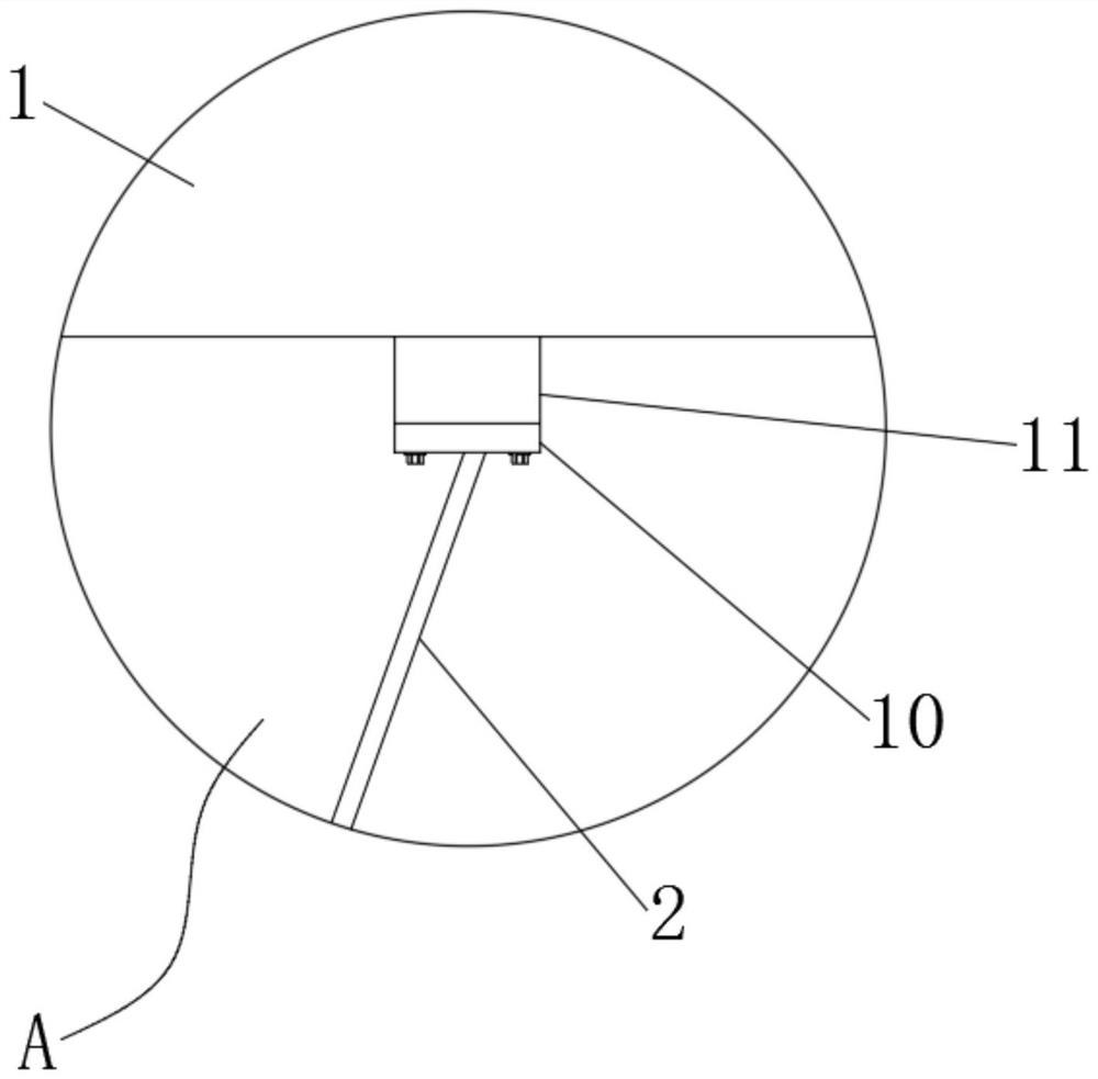
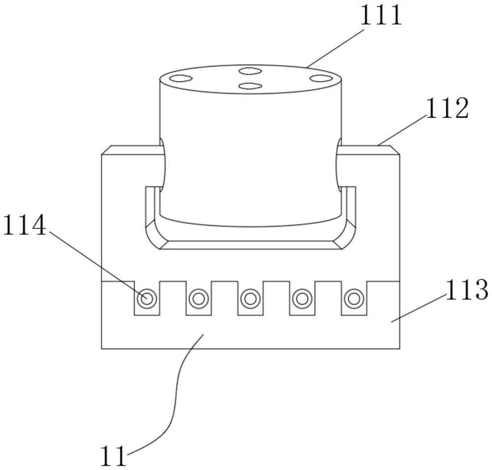
[0035] see figure 1 , figure 2 with image 3, the present invention provides a technical solution: a high-strength and low-cost stable rotating deceleration parachute, including a limit fixing sleeve 4 and a connecting chassis 8, the limiting fixing sleeve 4 is installed and fixed on the middle position of the lower end of the connecting chassis 8, and the limit is fixed The inner side of the lower end of the sleeve 4 is provided with a rotating collet 5, and the limit fixed sleeve 4 and the rotating collet 5 are fixedly connected through the fixed bearing bolt 7, and the two sides of the lower end of the rotating collet 5 are provided with adjusting and conflicting splints 6, which are connected The upper end of the chassis 8 is provided with a limit rope plate 9, and a support round rod 3 is arranged between the connection chassis 8 and the limit rope plate 9. The inner side of the limit rope plate 9 is located on the connection chassis 8 and is provided with a pull rope 2...
Embodiment 2
[0038] Such as figure 1 , figure 2 , Figure 4 , Figure 5 ,with Figure 8 , the limit rope disc 9 includes a metal sleeve 91, a lower end stub 92, a distance round rod 93 and a disc shell 94, the middle of the lower end of the disc shell 94 is provided with a lower stud 92, and the lower end of the lower stub 92 is provided with a spacing Round rod 93, the outer side of lower end stub 92 is positioned at the inner side of disk housing 94 and is provided with metal sleeve 91, and distance round rod 93 is installed and connected on the connection chassis 8, and the distance round rod 93 of limit rope dish 9 is welded and installed on Connect on the chassis 8, so that the distance round rods 93 are easy to support, so that the lower end short column 92 is convenient to be placed stably, so that the lower end short column 92 is convenient to support the disc shell 94 for use, because the metal sleeve 91 on the side of the disc shell 94, The metal sleeve 91 is convenient for ...
Embodiment 3
[0042] Such as figure 1 , figure 2 , Image 6 with Figure 9 , the rotating collet 5 includes a top sleeve 51, a shaft bolt round pipe 52, a shaft bolt through hole 53 and a bottom round pipe disc 54, and the top sleeve 51 is arranged in the middle of the upper end of the bottom round pipe disc 54, and the top sleeve 51 A shaft bolt round tube 52 is arranged inside the two ends, and a shaft bolt through hole 53 is arranged inside the top sleeve column 51 and the shaft bolt round tube 52, and the top sleeve column 51 and the shaft bolt round tube 52 are installed and connected to the fixed bearing bolt 7. The top sleeve column 51 and the shaft bolt round tube 52 of the rotating collet 5 are easy to install and fix the fixed bearing bolt 7 due to the internal shaft bolt through hole 53, so that the top sleeve column 51 and the shaft bolt round tube 52 are easy to rotate and use. Because of the bottom round pipe disc 54 at the lower end of the top sleeve 51, it is convenient ...
PUM
 Abstract
Description
Claims
Application Information
 - R&D Engineer
- R&D Manager
- IP Professional
- Industry Leading Data Capabilities
- Powerful AI technology
- Patent DNA Extraction
Browse by: Latest US Patents, China's latest patents, Technical Efficacy Thesaurus, Application Domain, Technology Topic, Popular Technical Reports.
© 2024 PatSnap. All rights reserved.Legal|Privacy policy|Modern Slavery Act Transparency Statement|Sitemap|About US| Contact US: help@patsnap.com


