Eureka AIR delivers breakthrough ideas for toughest innovation challenges, trusted by R&D personnel around the world.

Spliced display screen capable of preventing image deformation

A technology of image deformation and display screen, which is applied in the field of display screens, can solve problems such as poor splicing of display module panels, image deformation, and easy misalignment of display module panels, so as to reduce the risk of image deformation, uniform force, and improve The overall effect of splicing

Pending Publication Date: 2022-04-01
深圳市荣国星光电科技有限公司
View PDF0 Cites 0 Cited by
  • Summary
  • Abstract
  • Description
  • Claims
  • Application Information

AI Technical Summary

Problems solved by technology

[0003] In view of the related technologies mentioned above, the inventor believes that there are the following defects: the panel of the display module will generate heat during operation, and it will be locally deformed. The panel of the display module is easily dislocated, resulting in deformation of the image displayed on the display

Method used


Image

  • Spliced display screen capable of preventing image deformation
  • Spliced display screen capable of preventing image deformation
  • Spliced display screen capable of preventing image deformation

Examples


Embodiment 1

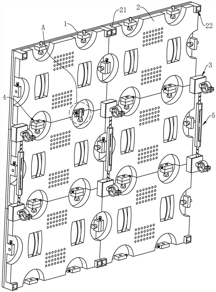
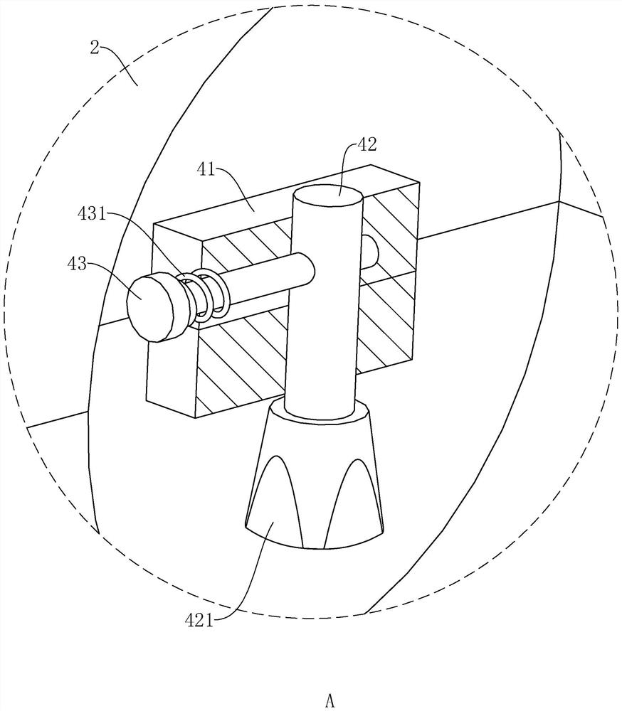
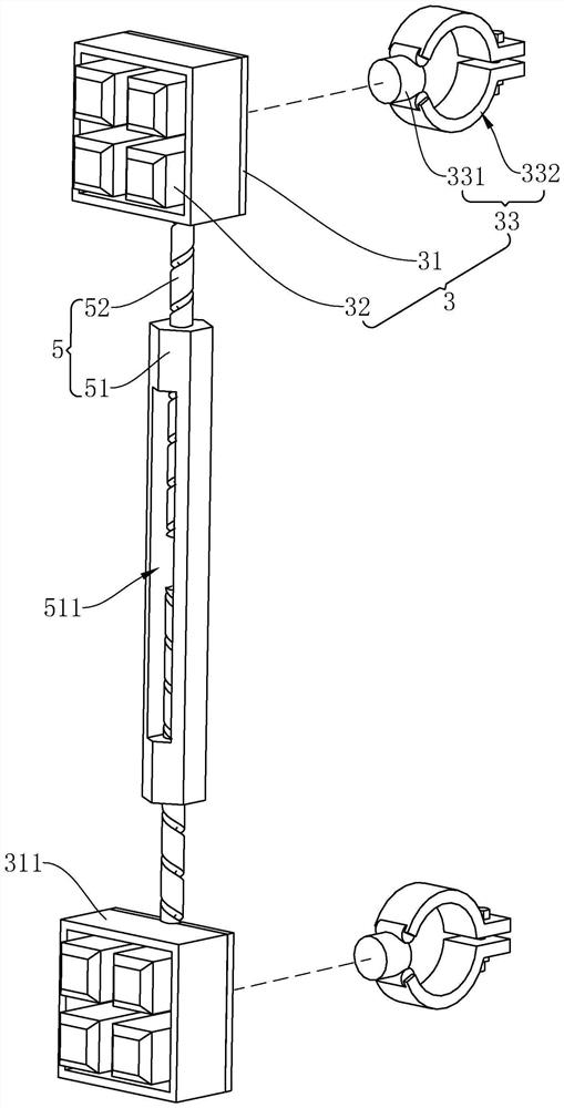
[0039] refer to figure 1 and figure 2A spliced ​​display screen for preventing image deformation includes a plurality of rectangular display screen bodies 1 and display bases 2, the number of display screen bodies 1 is equal to the number of display screen bases 2, the back of the display screen body 1 is connected to the display base 2 fixed connections. The display base 2 is integrally formed with a fixing seat 21 at four corners of the side facing away from the display body 1, and the end face of the fixing seat 21 away from the display body 1 is provided with a fixing hole 22 with a rectangular cross section; the adjacent display base 2 The fixing bases 21 are connected with a fastening connection mechanism 3, and the fastening connection mechanism 3 is used to fixedly connect the fixing bases 21 of two, three or four display screen bases 2. Adjacent fastening connection mechanisms 3 are also jointly connected with a telescopic mechanism 5 whose length can be adjusted. ...

Embodiment 2

[0054] refer to Figure 4 and Figure 5 , the difference from Embodiment 1 is that the connector 33 includes a rotating shaft 331 and a wall plate 333, the wall plate 333 replaces the hoop 332 in Embodiment 1, and the wall plate 333 is fixedly connected to the end of the rotating shaft 331 away from the bottom plate 31, The wallboard 333 is perpendicular to the rotating shaft 331. The wallboard 333 has a plurality of uniformly distributed through holes in the circumferential direction. The wallboard 333 is fixedly connected to the wall by passing bolts through the through holes, that is, the display screen is fixedly installed on the wall.


PUM


Abstract

The invention relates to the technical field of display screens, in particular to an image-deformation-preventing spliced display screen which comprises a display screen body, display screen bases are fixedly connected to the back face of the display screen body, fixing bases are fixedly arranged at the corners of the display screen bases, and fastening connecting mechanisms are connected to the fixing bases of the adjacent display screen bases. The fastening connection mechanism is used for fixedly connecting at least two fixing seats of the display screen bases; according to the display screen module panel, the splicing firmness of the adjacent display screen module panels can be improved, the dislocation risk of the display screen module panels can be reduced, and the display screen can normally display images.

Description

technical field [0001] The present application relates to the technical field of display screens, in particular to a spliced ​​display screen capable of preventing image deformation. Background technique [0002] The display screen is a flat-panel display, which is composed of small LED display module panels, used to display various information such as text, images, videos, video signals, etc. Outdoor media, exhibition halls, squares, performing arts venues, monitoring facilities, etc., for the public to watch. [0003] In view of the related technologies mentioned above, the inventor believes that there are the following defects: the panel of the display module will generate heat during operation, and it will be locally deformed. The panel of the display module is easily dislocated, resulting in distortion of the image displayed on the display. Contents of the invention [0004] In order to improve the splicing firmness of adjacent display module panels, reduce the risk...

Claims


Application Information

Patent Timeline
IPC IPC(8): F16M13/02F16M11/04G09F9/30
Inventor 周凯凯周明明葛力仁杨帅
Owner 深圳市荣国星光电科技有限公司
Why Eureka
Eureka Blog
Learn More