Eureka AIR delivers breakthrough ideas for toughest innovation challenges, trusted by R&D personnel around the world.

Cast-in-place beam formwork tooling and construction method for dismantling cast-in-place beam formwork

A technology of cast-in-place beams and templates, applied in bridges, bridge construction, erection/assembly of bridges, etc., can solve problems such as inconvenient operation, and achieve the effects of increasing splicing firmness, reducing frictional resistance, and uniform force

Inactive Publication Date: 2018-03-30
天津市东泽天润建工科技有限公司
View PDF6 Cites 5 Cited by
  • Summary
  • Abstract
  • Description
  • Claims
  • Application Information

AI Technical Summary

Problems solved by technology

However, if the construction terrain is complex, it is not convenient to operate

Method used


Image

  • Cast-in-place beam formwork tooling and construction method for dismantling cast-in-place beam formwork
  • Cast-in-place beam formwork tooling and construction method for dismantling cast-in-place beam formwork
  • Cast-in-place beam formwork tooling and construction method for dismantling cast-in-place beam formwork

Examples


Embodiment 1

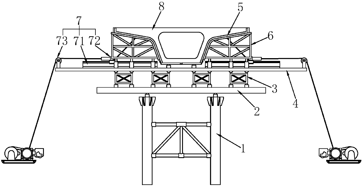
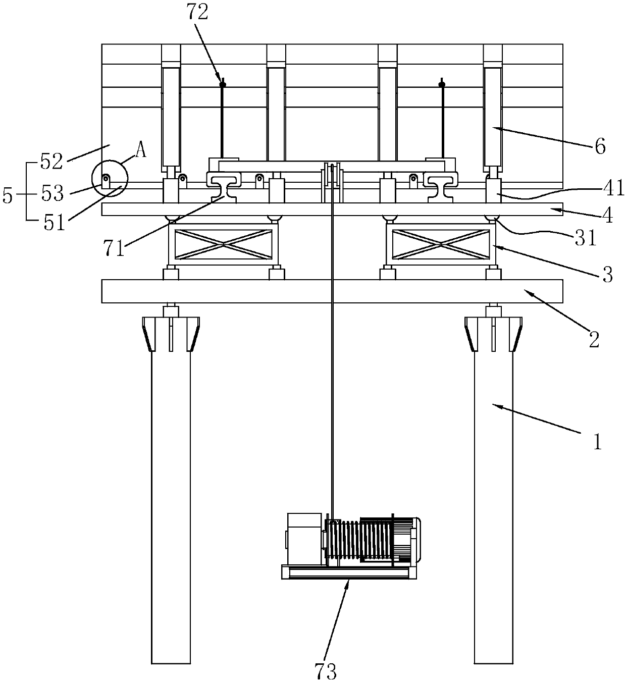
[0037] Embodiment 1: A kind of cast-in-place beam formwork tooling, such as figure 1 and figure 2 As shown, it includes a buttress 1 supported on the ground, on which a support beam 2 welded by a plurality of steel plates is fixed as the bottom support of the cast-in-place beam 8 . Several jacks are placed on the support beam 2, and some distribution beams 3 welded by steel plates are installed on the jacks, and a bowl-shaped support column 31 is installed on the top of the distribution beam 3. Some beams 4 parallel to the ground are installed above the support column 31. The beams 4 are perpendicular to the cast-in-place beams 8. Several jacks are installed at intervals on the beams 4 as temporary supports 41. Sand cylinders can also be used here instead.

[0038] The template 5 is installed above the temporary support 41, and the specific steps are: placing the bottom mold 51 above the jack at the middle position of the beam 4, and the bottom mold 51 is divided into two pa...

Embodiment 2

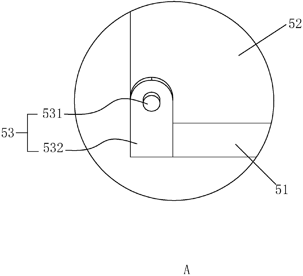
[0043] Embodiment 2: A construction method for removing cast-in-place beam formwork tooling: when the cast-in-place beam 8 is solidified and the formwork 5 is disassembled, the bolts between the side formwork 52 and the bottom formwork 51 are loosened in advance; the hasp 532 is turned over to make The hasp 532 is unlocked from the locking post 531 . The jack or the sand cylinder used as the temporary support 41 release the pressure, and the side form support 6 is disassembled.

[0044] The sliding block 722 is placed on the sliding rail 71 in advance, and is slidably connected with the sliding rail 71 , and the elastic steel plate group 732 is welded and fixed to the sliding block 722 . The traction line 733 is bolted in the middle of the elastic steel plate group 732 in advance, and the traction machine 734 is driven or the traction line 733 is pulled to further adjust the traction line 733 to be located in the middle of the elastic steel plate group 732 . Taking the positi...


PUM


Abstract

The invention relates to a cast-in-place box beam formwork tooling and a construction method for dismantling the cast-in-place beam formwork. The cast-in-place beam formwork tooling comprises supportpiers, a cross beam on the support piers, and a temporary support on the cross beam. The temporary support is provided with a bottom die which comprises two parts. The two sides of the bottom die areconnected with side dies. The side dies are supported by adopting brackets. Traction systems are arranged between the two ends in the length direction of the side dies and the cross beam. The tractionsystems comprise slide rails arranged in the length direction of the cross beam, traction assemblies that slide along the slide rails and are detachably connected with the side dies, and towing devices that drive the traction assemblies to slide. During dismantling, the temporary support is lowered and thus the temporary support is detached from the bottom die; the traction assemblies are connected to the side dies, and are driven to slide along the slide rails by the towing devices, and thus the side dies are detached from a cast-in-situ beam; and hasps are overturned, the traction assemblies are connected to the hasps, and are driven to slide along the slide rails by the towing devices, and thus the bottom die is detached from the cast-in-situ beam. The dismantling method has the characteristics that disassembly is convenient and the side dies and the bottom die are favorably separated from the cast-in-place beam.

Description

technical field [0001] The invention relates to the field of concrete cast-in-place box girders, in particular to a cast-in-place box girder formwork tooling and a construction method for removing the cast-in-place beam formwork. Background technique [0002] In bridge construction, in order to speed up the construction progress, box girder structure is usually adopted. For large continuous bridges, it is more convenient to use cast-in-place box girders for construction. During construction, it is necessary to level the ground in advance; then set up floor supports, install beams and distribution longitudinal beams; lay bottom formwork and side forms; pour concrete; after the concrete is formed, remove the formwork. Usually when the formwork is removed, manual assistance is required to separate the side formwork and bottom formwork from the poured concrete. However, if the construction terrain is more complex, it is not convenient to operate. Contents of the invention ...

Claims


Application Information

Patent Timeline
Patent Type & Authority Applications(China)
IPC IPC(8): E01D21/00
CPCE01D21/00
Inventor 燕勋陈阵曹桐
Owner 天津市东泽天润建工科技有限公司
Why Eureka
Eureka Blog
Learn More