Cast-in-place beam formwork tooling and construction method for dismantling cast-in-place beam formwork
A construction method and technology of cast-in-place beams, which are applied in bridges, bridge construction, erection/assembly of bridges, etc., can solve problems such as inconvenient operation, and achieve the effects of increasing splicing firmness, reducing frictional resistance, and uniform force
- Summary
- Abstract
- Description
- Claims
- Application Information
AI Technical Summary
Problems solved by technology
Method used
Image
Examples
Embodiment 1
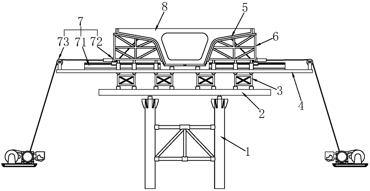
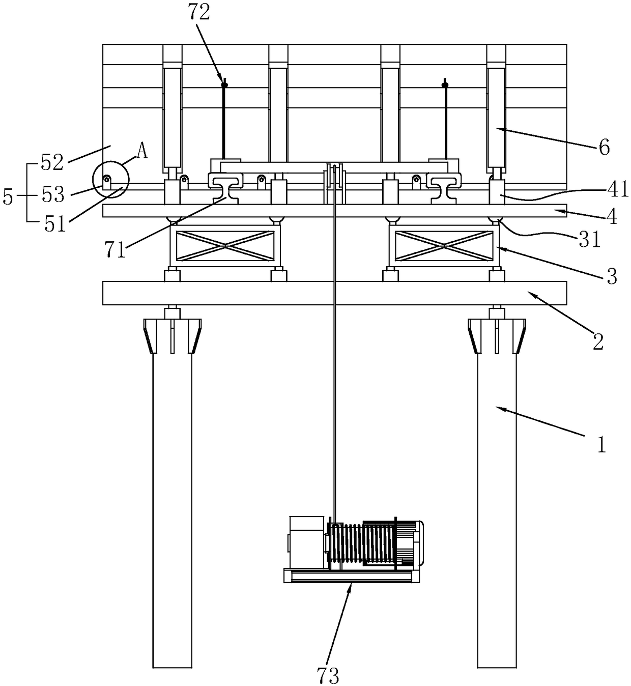
[0037] Embodiment 1: A kind of cast-in-place beam formwork tooling, such as figure 1 with figure 2 As shown, it includes a buttress 1 supported on the ground, on which a support beam 2 welded by a plurality of steel plates is fixed as the bottom support of the cast-in-place beam 8 . Several jacks are placed on the support beam 2, and some distribution beams 3 welded by steel plates are installed on the jacks, and a bowl-shaped support column 31 is installed on the top of the distribution beam 3. Some beams 4 parallel to the ground are installed above the support column 31. The beams 4 are perpendicular to the cast-in-place beams 8. Several jacks are installed at intervals on the beams 4 as temporary supports 41. Sand cylinders can also be used here instead.
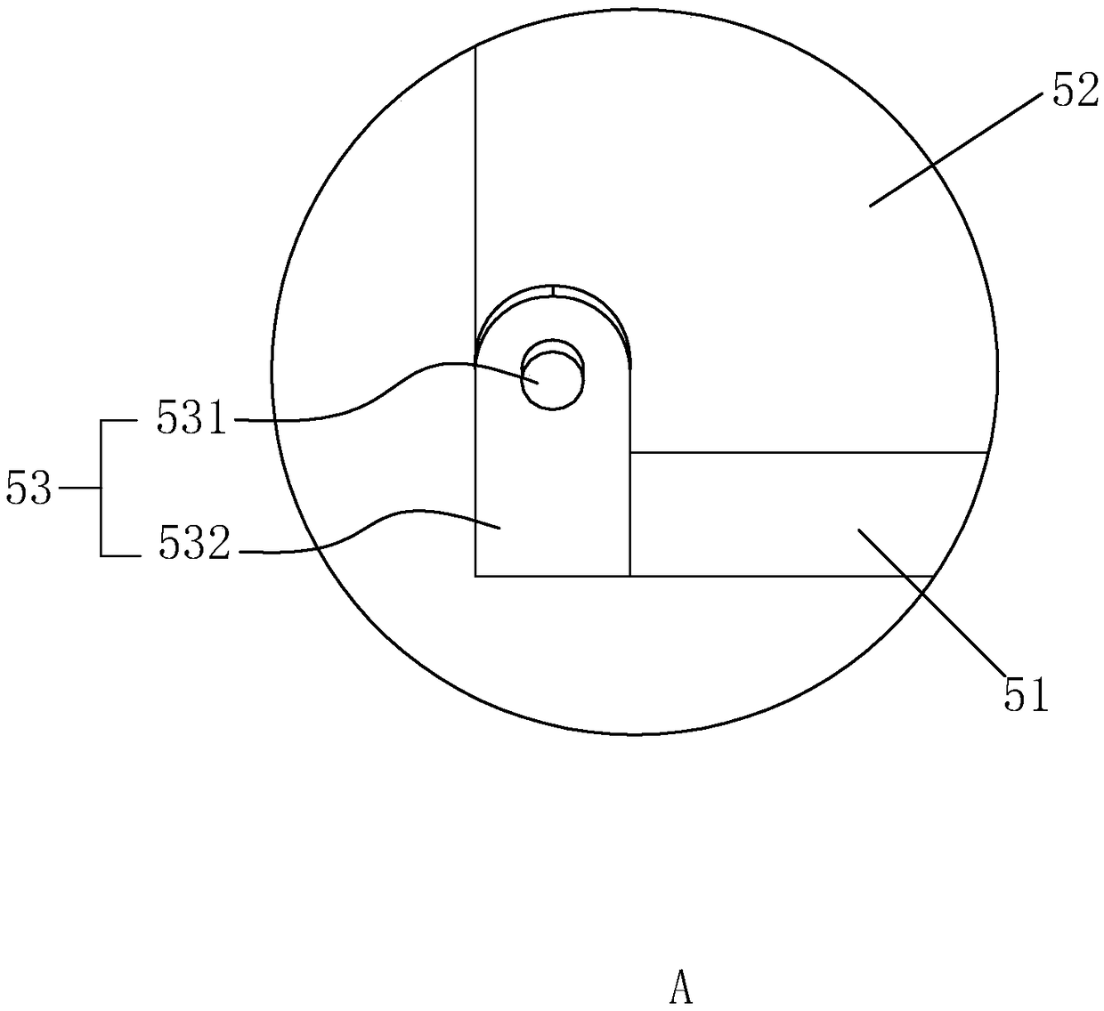
[0038] The template 5 is installed above the temporary support 41, and the specific steps are: placing the bottom mold 51 above the jack at the middle position of the beam 4, and the bottom mold 51 is divided into two p...
Embodiment 2
[0043] Embodiment 2: A construction method for removing cast-in-place beam formwork tooling: when the cast-in-place beam 8 is solidified and the formwork 5 is disassembled, the bolts between the side formwork 52 and the bottom formwork 51 are loosened in advance; the hasp 532 is turned over to make The hasp 532 is unlocked from the locking post 531 . The jack or the sand cylinder used as the temporary support 41 release the pressure, and the side form support 6 is disassembled.
[0044] The sliding block 722 is placed on the sliding rail 71 in advance, and is slidably connected with the sliding rail 71 , and the elastic steel plate group 732 is welded and fixed to the sliding block 722 . The traction line 733 is bolted in the middle of the elastic steel plate group 732 in advance, and the tractor 734 is driven or the traction line 733 is pulled to further adjust the traction line 733 to be located in the middle of the elastic steel plate group 732 . Taking the position of the...
PUM
 Abstract
Description
Claims
Application Information
 - R&D Engineer
- R&D Manager
- IP Professional
- Industry Leading Data Capabilities
- Powerful AI technology
- Patent DNA Extraction
Browse by: Latest US Patents, China's latest patents, Technical Efficacy Thesaurus, Application Domain, Technology Topic, Popular Technical Reports.
© 2024 PatSnap. All rights reserved.Legal|Privacy policy|Modern Slavery Act Transparency Statement|Sitemap|About US| Contact US: help@patsnap.com


