
Rotor spinning power-off integral head-keeping system

A rotor spinning and electronic control system technology, applied in the field of rotor spinning, can solve the problems of easily damaged UPS power supply, reduced spinning output, inconvenient installation, etc., to reduce labor intensity, increase imitation yarn output, and ensure integrity Effect

Active Publication Date: 2022-04-01
ZHEJIANG JINMA AUTOMATION TECH CO LTD
View PDF6 Cites 0 Cited by
  • Summary
  • Abstract
  • Description
  • Claims
  • Application Information

AI Technical Summary

Problems solved by technology

[0002] For rotor spinning equipment, due to the large number of spindles, the workload of artificial yarn spinning is heavy. When the power grid suddenly fails, the rotor spinning equipment cannot keep the yarn as a whole. Worker's labor intensity, but also reduce spinning output
[0003] Due to the loss of the original power supply system of the electronic control system when the power is cut off, it cannot work normally; simply adding a UPS power supply is very easy to damage the UPS power supply in the textile factory environment
At present, the solution of some manufacturers is: add a capacitive energy storage unit in the electric control of the machine head and the middle section. The energy storage unit is inconvenient to install, high cost, and inconvenient to maintain, etc.

Method used


Image

  • Rotor spinning power-off integral head-keeping system
  • Rotor spinning power-off integral head-keeping system

Examples


Embodiment Construction

[0023] The following will clearly and completely describe the technical solutions in the embodiments of the present invention with reference to the accompanying drawings in the embodiments of the present invention. Obviously, the described embodiments are only some, not all, embodiments of the present invention. Based on the embodiments of the present invention, all other embodiments obtained by persons of ordinary skill in the art without creative efforts fall within the protection scope of the present invention.

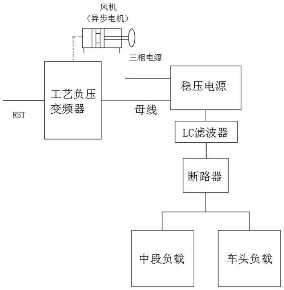
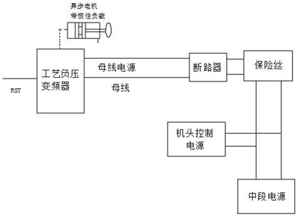
[0024] An overall head retention system for rotor spinning when the power is off, including a process negative pressure motor, a machine head controller and a middle control board. The process negative pressure motor is connected to the fan. When the power is off, the inertia kinetic energy of the fan is converted by the motor and the process negative pressure frequency converter. For electric energy, the converted electric energy is continuously supplied to the bus...


PUM


Abstract

The invention discloses a rotor spinning power-off integral head leaving system which comprises a process negative pressure motor, a machine head controller and a middle section control panel, the process negative pressure motor is connected with a fan, inertia kinetic energy of the fan is converted into electric energy through the motor and a process negative pressure frequency converter during power off, and the converted electric energy is continuously supplied to a bus of an electric control system; the machine head controller controls the winding motor and the yarn guiding motor. And the middle-section control plate controls the cotton feeding roller. An additional energy storage device is not needed, the power supply problem of the electric control system when the rotor spinning equipment is powered off is effectively solved, the cost is greatly saved, the reliability is improved, the electric control system continuously works and completes the overall head remaining function when the rotor spinning equipment is powered off externally, overall head making-up is not needed when rotor spinning equipment is started again, and the efficiency is improved. The labor intensity of workers is greatly reduced, the high-imitation yarn yield is improved, and the completeness of a power supply system is guaranteed.

Description

technical field [0001] The invention belongs to the technical field of rotor spinning, and relates to a power-off integral head retention system for rotor spinning. Background technique [0002] For rotor spinning equipment, due to the large number of spindles, the workload of artificial yarn spinning is heavy. When the power grid suddenly fails, the rotor spinning equipment cannot keep the yarn as a whole. The labor intensity of the workers also reduces the spinning output. [0003] When the power is cut off, the original power supply system of the electronic control system is missing, which makes it unable to work normally; simply adding UPS power supply is very easy to damage the UPS power supply in the textile factory environment. At present, the solution of some manufacturers is: add a capacitive energy storage unit in the electric control of the machine head and the middle section. The energy storage unit has disadvantages such as inconvenient installation, high cost...

Claims


Application Information

Patent Timeline
Patent Type & Authority Applications(China)
IPC IPC(8): D01H4/50
Inventor 杨亚江肖锋赵翔
Owner ZHEJIANG JINMA AUTOMATION TECH CO LTD
Learn More