


Quick Research
Generate reliable direction feasibility study reports for your R&D in just a few steps.

Technical Q&A
Discover and master advanced knowledge NOW. Basics, ideas, possibilities, all at once.

Find Solutions
As an expert in R&D theories, this can generate solutions to your technical problems instantly.

Evaluate Feasibility
Analyze your overall solution with one click, know your potential R&D risks in advance.

Monitor Landscape
Get weekly tech updates, stay abreast of the latest tech innovations and key insights.
Lamp and lamp control method
A control method and lamp technology, which is applied in the field of lighting, can solve the problems of high switching frequency, reduced lifespan, and low reliability of light source modules, and achieve the effect of reducing the probability of on-off actions
- Summary
- Abstract
- Description
- Claims
- Application Information
AI Technical Summary
Problems solved by technology
Method used
Image

Examples
Embodiment 1
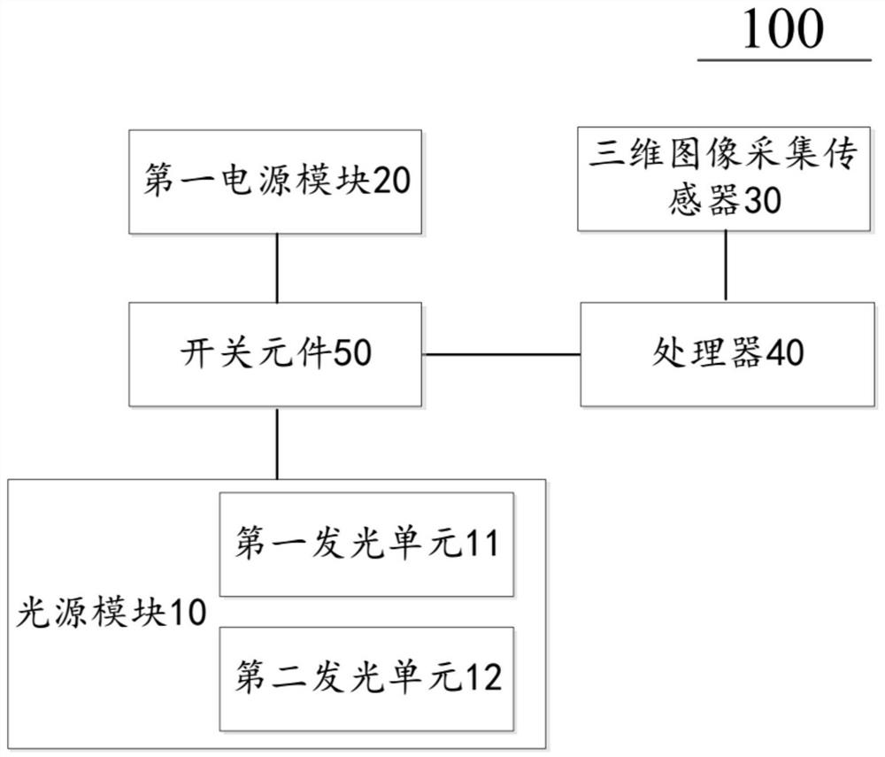
[0026] An embodiment of the present invention provides a lamp, such as figure 1 As shown, the lamp 100 may include: a light source module 10 , a first power supply module 20 , a three-dimensional image acquisition sensor 30 and a processor 40 . The first power supply module 20 is connected to the light source module 10, and outputs power to the light source module 10, and the light source module 10 is used for emitting light. The 3D image acquisition sensor 30 is arranged in the irradiated space of the lamp 100 and used for collecting 3D image information of the irradiated space of the lamp 100 . The processor 40 is connected to the 3D image acquisition sensor 30 , and determines the scene of the irradiable area of the lamp according to the 3D image information collected by the 3D image acquisition sensor 30 to determine the target lighting mode of the lamp 100 . In the embodiment of the present invention, what the three-dimensional image acquisition sensor 30 collects is t...
Embodiment 2
[0049] An embodiment of the present invention provides a method for controlling a lamp 100 . The lamp 100 may be the lamp 100 in Embodiment 1, or other lamps 100 .
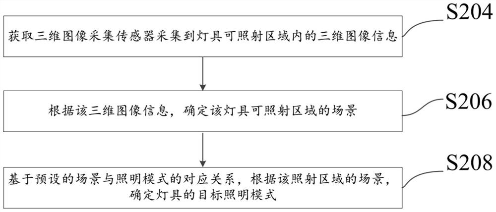
[0050] In one embodiment, as figure 2 As shown, the control method of the lamp 100 includes:
[0051] S204: Obtain the three-dimensional image information collected by the three-dimensional image acquisition sensor 30 within the irradiable area of the lamp 100 .
[0052] S206: According to the three-dimensional image information, determine the scene of the illuminated area of the lamp 100 .
[0053] S208: Based on the preset correspondence between scenes and lighting modes, determine the target lighting mode of the lamp 100 according to the scene of the irradiation area.
[0054] In the control method of the lamp 100 in the embodiment of the present invention, a three-dimensional image acquisition sensor 30 is provided in the irradiable area of the lamp 100, and after the three-dimensional image acquisiti...
PUM
 Abstract
Description
Claims
Application Information
 - R&D Engineer
- R&D Manager
- IP Professional
- Industry Leading Data Capabilities
- Powerful AI technology
- Patent DNA Extraction
Browse by: Latest US Patents, China's latest patents, Technical Efficacy Thesaurus, Application Domain, Technology Topic, Popular Technical Reports.
© 2024 PatSnap. All rights reserved.Legal|Privacy policy|Modern Slavery Act Transparency Statement|Sitemap|About US| Contact US: help@patsnap.com