
Semiconductor wafer test structure and test method

A technology of test structure and test method, which is applied in the direction of semiconductor/solid-state device test/measurement, electrical components, circuits, etc., can solve the problems such as the decrease of the linearity of the resistance mismatch curve, the failure of the resistance mismatch curve, and the influence, and achieve a simple structure Effect

Pending Publication Date: 2022-03-29
HUA HONG SEMICON WUXI LTD +1
View PDF0 Cites 0 Cited by
  • Summary
  • Abstract
  • Description
  • Claims
  • Application Information

AI Technical Summary

Problems solved by technology

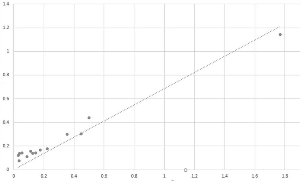
[0008] figure 2 In the resistance mismatch curve shown, the X-axis is used to represent the size of the resistance, the unit is 1 / um, and the Y-axis is used to represent the matching degree of the resistance. The linearity of the resistance mismatch curve is proportional to the process stability, but Since the probes used in the probe test machine also have resistance, the resistance value of the probe will affect the test results when performing the above resistance mismatch test, especially when dealing with small resistance values, making the linearity of the resistance mismatch curve In turn, the resistance mismatch curve cannot reflect the stability of the process through linearity, and the test purpose cannot be achieved

Method used


Image

  • Semiconductor wafer test structure and test method
  • Semiconductor wafer test structure and test method
  • Semiconductor wafer test structure and test method

Examples


Embodiment Construction

[0037] The following will clearly and completely describe the technical solutions in the embodiments of the present invention with reference to the accompanying drawings in the embodiments of the present invention. Obviously, the described embodiments are only some, not all, embodiments of the present invention. Based on the embodiments of the present invention, all other embodiments obtained by persons of ordinary skill in the art without making creative efforts belong to the protection scope of the present invention.

[0038] It should be noted that, in the case of no conflict, the embodiments of the present invention and the features in the embodiments can be combined with each other.

[0039] The present invention will be further described below in conjunction with the accompanying drawings and specific embodiments, but not as a limitation of the present invention.

[0040] Such as image 3 As shown, the technical solution of the present invention includes a test structur...


PUM


Abstract

The invention provides a test structure of a semiconductor wafer, which comprises a first test pad, a second test pad, a third test pad and a fourth test pad, two ends of the first resistor are respectively connected with the first test pad and the second test pad; two ends of the second resistor are respectively connected with the third test pad and the fourth test pad; and two ends of the third resistor are respectively connected with the second test pad and the third test pad. The technical scheme of the invention has the beneficial effects that the influence of a probe of a probe test machine on the test result of the resistance test structure on the semiconductor wafer is eliminated, the structure is simple, the overall layout of the existing test structure is not changed, the area occupied by the test structure on the wafer is not influenced, and adjustment and adaptation can be carried out according to the wafer layout.

Description

technical field [0001] The invention relates to the technical field of semiconductor testing, in particular to a testing structure and testing method of a semiconductor wafer. Background technique [0002] In the process of semiconductor wafer processing, in order to monitor the processing technology, test structures are usually set on some predetermined positions of the wafer. These test structures are processed together with the wafer process and the device structure on the wafer. During the test phase Performing performance tests on these test structures can reflect whether there is a problem in the processing technology of the wafer. Since these test structures are not the final products required by the factory, it is impossible to occupy too much space on the wafer, so complex test circuits cannot be applied to these test structures. On the basis of satisfying the amount of data expressed, often only Using some simple circuit structures, such as resistance mismatch tes...

Claims


Application Information

Patent Timeline
IPC IPC(8): H01L21/66
CPCH01L22/30H01L22/34
Inventor 李岩武洁许新贵何鹏
Owner HUA HONG SEMICON WUXI LTD
Learn More