
Relative torsion angle measuring device based on timestamp

A technology for measuring devices and torsion angles, which is applied in the directions of measuring devices, torque measurement, power measurement, etc., can solve the problem that the relative torsion angle cannot be integrated, and achieve the effect of satisfactory accuracy and simple and reliable system

Pending Publication Date: 2022-03-29
中国船舶重工集团公司第七0三研究所
View PDF0 Cites 0 Cited by
  • Summary
  • Abstract
  • Description
  • Claims
  • Application Information

AI Technical Summary

Problems solved by technology

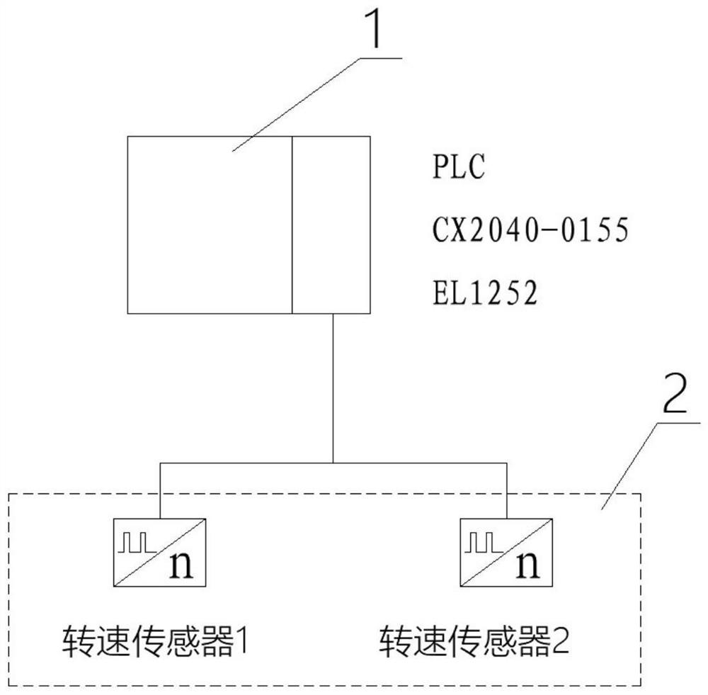
[0004] The purpose of the present invention is to solve the problem of measuring the relative torsion angle of two rotating shafts, which cannot be integrated in the product and the control system, a relative torsion angle measurement device based on time stamp

Method used


Image

  • Relative torsion angle measuring device based on timestamp
  • Relative torsion angle measuring device based on timestamp

Examples


Embodiment Construction

[0012] The present invention will be further described below in conjunction with the accompanying drawings and specific embodiments.

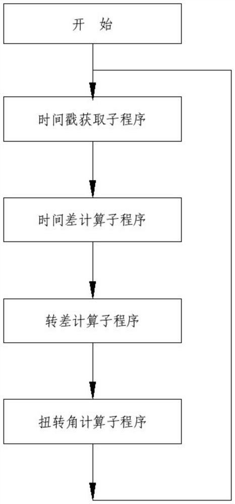
[0013] like figure 1 As shown, a relative torsion angle measurement device based on time stamp involved in this embodiment, which integrates the torsion angle measurement function, realizes a relative torsion angle measurement method based on time stamp, including a PLC control module 1 and a speed sensor 2, The signal of the rotational speed sensor 2 enters the PLC control module 1, and the PLC module 1 is used to complete the acquisition of pulse signal frequency and time stamp and calculate the time stamp difference and rotational speed difference, and then calculate the relative torsion angle.

[0014] As an embodiment of the present invention, the PLC control module 1 includes Beckhoff CX2040-0155 and EL1252, and the CX2040-0155 is the acquisition and calculation control core of the entire system. The controller, the EL1252 module in the ...


PUM


Abstract

The invention provides a timestamp-based relative torsion angle measuring device. The timestamp-based relative torsion angle measuring device comprises a PLC (Programmable Logic Controller) control module and a rotating speed sensor, and the PLC control module is connected with the rotating speed sensor. According to the invention, a phase difference measurement function integrated in a product can be realized, and the system can be expanded into a control system so as to realize uniform distribution of meshing positions or fixation of meshing positions. The method is simple and reliable, and the precision meets conventional requirements.

Description

technical field [0001] The invention relates to the field of relative torsion angle measurement, in particular to a time stamp-based relative torsion angle measurement device. Background technique [0002] In synchronous clutches and other requirements that require obtaining the relative torsion angle of two rotating shafts, it is necessary to measure the relative torsion angle of the two rotating shafts online in real time, and then integrate it into the product and use it for control purposes, such as evenly distributing the utilization rate of each meshing position to extend service life or fix the meshing position to obtain the best dynamic balance effect, etc. [0003] Currently, such measurement methods use oscilloscopes or computers, which cannot be integrated into products and control systems. Contents of the invention [0004] The object of the present invention is to solve the problem that measuring the relative torsion angle of two rotating shafts cannot be int...

Claims


Application Information

Patent Timeline
Patent Type & Authority Applications(China)
IPC IPC(8): G01L3/00
CPCG01L3/00
Inventor 贾双权杨佳彬李超陈业明刘江
Owner 中国船舶重工集团公司第七0三研究所
Learn More