
Oil injection device and parameter calibration method of oil injection device

A fuel injection device and parameter calibration technology, which is applied to fuel injection devices, measuring devices, charging systems, etc., can solve the problems of low air utilization, reduce smoke generation, promote uniformity, and enhance flow field strength Effect

Active Publication Date: 2022-03-29
WEICHAI POWER CO LTD
View PDF8 Cites 1 Cited by
  • Summary
  • Abstract
  • Description
  • Claims
  • Application Information

AI Technical Summary

Problems solved by technology

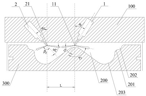
However, since the vortex in the central area of ​​the combustion chamber is relatively small, and the oil beams sprayed by the injector are mainly distributed in the edge area of ​​the combustion chamber, there is no mixing of fuel and gas in the central area, and the air utilization rate is low.

Method used


Image

  • Oil injection device and parameter calibration method of oil injection device
  • Oil injection device and parameter calibration method of oil injection device
  • Oil injection device and parameter calibration method of oil injection device

Examples


Embodiment Construction

[0034] The present invention will be further described in detail below in conjunction with the accompanying drawings and embodiments. It should be understood that the specific embodiments described here are only used to explain the present invention, but not to limit the present invention. In addition, it should be noted that, for the convenience of description, only some structures related to the present invention are shown in the drawings but not all structures.

[0035] In the description of the embodiments of the present invention, unless otherwise specified and limited, the terms "connected", "connected" and "fixed" should be interpreted in a broad sense, for example, it can be a fixed connection or a detachable connection, or Integrate; can be mechanical connection, can also be electrical connection; can be directly connected, can also be indirectly connected through an intermediary, can be the internal communication of two components or the interaction relationship betw...


PUM


Abstract

The invention belongs to the technical field of diesel engines, and discloses an oil injection device and a parameter calibration method of the oil injection device.The oil injection device comprises a first oil injector and a second oil injector which are obliquely arranged on a cylinder cover, the first oil injector comprises a first oil injection nozzle, and the first oil injection nozzle is located in a combustion chamber; a plurality of first oil spraying holes are formed in the circumferential direction of the first oil spraying nozzle, so that oil beams can be conveniently sprayed to the edge area of the combustion chamber; the second oil sprayer comprises a second oil spraying nozzle, the second oil spraying nozzle is located in the combustion chamber, a second oil spraying hole and a third oil spraying hole are formed in the second oil spraying nozzle, the second oil spraying hole faces the center area of the combustion chamber so that oil beams sprayed out of the second oil spraying nozzle can point to the center area of the combustion chamber, and the third oil spraying hole faces the annular protrusion in the combustion chamber. And the oil beam sprayed by the second oil spray nozzle points to the annular bulge of the combustion chamber.

Description

technical field [0001] The invention relates to the field of technical diesel engines, in particular to a fuel injection device and a parameter calibration method of the fuel injection device. Background technique [0002] A combustion chamber is arranged on the piston, and a fuel injector is vertically arranged on the cylinder head, and the nozzle of the fuel injector is located in the central area of ​​the combustion chamber, thereby injecting fuel into the combustion chamber. The gas is taken in through the intake port, forming a spiral vortex movement along the cylinder wall in the cylinder body of the cylinder, and the vortex ratio gradually decreases from the edge area of ​​the cylinder block to the central area. During the operation of the piston, the injector starts to inject oil when the piston is close to the compression top dead center, and forms an entrainment effect at the end of the oil beam, and the oil beam mixes with the gas to form a combustible mixture. H...

Claims


Application Information

Patent Timeline
Patent Type & Authority Applications(China)
IPC IPC(8): F02M39/00F02M65/00
CPCF02M39/00F02M65/00
Inventor 庞斌王德成刘晓鑫胡晓艳李万里陈荣祥程旭李志杰
Owner WEICHAI POWER CO LTD
Learn More