
Method for treating water seepage of jet grouting pile

A treatment method and technology of rotary grouting piles, which can be applied in the direction of sheet pile walls, buildings, protective devices, etc., can solve the problem of limited pilot hole space, unsatisfactory water sealing effect of ultra-high pressure rotary grouting piles and occlusal piles, ultra-high pressure rotary grouting piles, etc. The construction quality of the water-stop curtain puts forward higher requirements and other issues

Pending Publication Date: 2022-03-29
BEIJING MUNICIPAL CONSTR
View PDF4 Cites 0 Cited by
  • Summary
  • Abstract
  • Description
  • Claims
  • Application Information

AI Technical Summary

Problems solved by technology

According to the water-stop test of Beijing subway stations, the water-stop effect of ultra-high pressure jet grouting piles and occlusal piles is not ideal
[0003] At this stage, the combination of ultra-high pressure jet grouting piles and side piles is mostly used as the enclosure and water-stop structure of underground excavation stations. However, the space of pilot tunnels in subway underground excavation stations is limited. Higher requirements for construction quality
When the ultra-high-pressure rotary grouting piles are lifted too fast or the vertical accuracy is not enough, the bite will not be tight. At this time, the groundwater existing in the formation will flow out into the foundation pit along the seepage channel on the pile body, affecting the station. Earthwork and structural construction, and the setting of emergency dewatering wells outside the station is greatly affected by site conditions, and it is not easy to form closed precipitation. Therefore, it is necessary to invent a treatment method to deal with the water seepage problem of ultra-high pressure jet grouting piles

Method used


Image

  • Method for treating water seepage of jet grouting pile
  • Method for treating water seepage of jet grouting pile
  • Method for treating water seepage of jet grouting pile

Examples


Embodiment 1

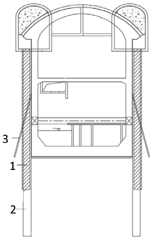
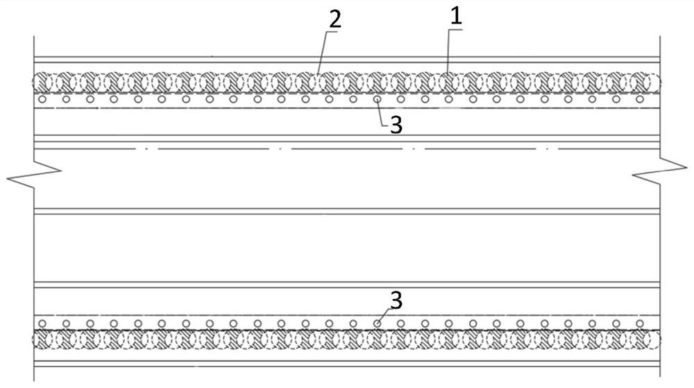
[0044] Refer below figure 1 and figure 2 To describe the water seepage treatment during the construction of the subway station.

[0045] In the construction site of the middle plate of the subway, after the excavation of the first layer of earthwork on the platform layer of the subway is completed, when the ultra-high pressure rotary grouting pile 1 is defective or the pile body seeps due to the loose engagement with the bored pile 2, according to the water seepage point and its water gushing degree, combined with the site construction conditions, determine the location of the required dewatering well 3, the dewatering depth is 5-10m, and the inclination angle is 15-30°; select several PVC dewatering well pipes with a diameter of 100mm;

[0046] Corresponding to the jet grouting pile 1, it is laid longitudinally along the length direction of the station. At the wall structure inside the jet grouting pile 1, the 3 pipe holes of the dewatering well are drilled obliquely to the...


PUM

PropertyMeasurementUnit
Diameteraaaaaaaaaa

Abstract

The invention provides a jet grouting pile water seepage treatment method which comprises the following steps: measuring and positioning: measuring and positioning a water seepage point and a water gushing degree thereof, and determining a driving position and a construction requirement of a required precipitation well; pipe holes are drilled, specifically, dewatering well pipe holes obliquely penetrating to the outer side of the jet grouting pile are drilled in the inner side of the jet grouting pile, and the dewatering well pipe holes with the required number are drilled in sequence; the precipitation well is installed, specifically, the precipitation well is inserted into the formed precipitation well pipe hole; and water seepage treatment: after entering the precipitation well pipe, water seepage is pumped and discharged to a vertical shaft sedimentation tank through a water pump. According to the method, the small-caliber tube well is specifically arranged at the water seepage part for dewatering, the problem of water seepage of the pile body caused by defects of the ultrahigh-pressure jet grouting pile or untight occlusion is effectively solved, and waterless operation of the station foundation pit is guaranteed.

Description

technical field [0001] The invention relates to the field of underground construction engineering structures, in particular to a method for treating water seepage of rotary jetting piles. Background technique [0002] When underground engineering construction restricts the use of precipitation to control groundwater seepage, the water-stop curtain is an effective water-stop measure in non-precipitation construction. According to the water-stop test of Beijing subway stations, the water-stop effect of ultra-high pressure jet grouting piles and occlusal piles is not ideal. [0003] At this stage, the combination of ultra-high pressure jet grouting piles and side piles is mostly used as the enclosure and water-stop structure of underground excavation stations. However, the space of pilot tunnels in subway underground excavation stations is limited. The construction quality puts forward higher requirements. When the ultra-high-pressure rotary grouting piles are lifted too fast...

Claims


Application Information

Patent Timeline
IPC IPC(8): E02D19/10E02D5/46E02D19/20E02D31/02
CPCE02D19/10E02D5/46E02D19/20E02D31/02
Inventor 花延杰郑昊马景霞刘文倩董亚航商佳俊李想田忠豪
Owner BEIJING MUNICIPAL CONSTR
Learn More