
Aluminum-based circuit board etching equipment for LED lamp

A technology for LED lamps and etching equipment, which is applied to printed circuits, printed circuit manufacturing, and chemical/electrolytic methods to remove conductive materials, etc., can solve the problems of reducing the production speed of aluminum-based circuit boards, cumbersome operations, and increasing etching processing time. , to achieve the effect of shortening the etching treatment time, spraying uniformly, and improving the etching effect

Pending Publication Date: 2022-03-25
吴世谋
View PDF0 Cites 2 Cited by
  • Summary
  • Abstract
  • Description
  • Claims
  • Application Information

AI Technical Summary

Problems solved by technology

[0003] At present, when the aluminum-based circuit board is etched, the aluminum-based circuit board is usually moved to the etching equipment through an external conveyor belt, and then the surface of the aluminum-based circuit board is sprayed with an etching solution, but this can only be done to the aluminum-based circuit board. One side of the board is processed, and then the aluminum-based circuit board needs to be removed from the etching equipment and turned over 180°, and then transported to the etching equipment again to be sprayed with etching solution to complete the etching process of the aluminum-based circuit board , which leads to the need to separately etch the two sides of the aluminum-based circuit board during the etching process, which is cumbersome to operate and increases the etching processing time, thus reducing the production speed of the aluminum-based circuit board

Method used


Image

  • Aluminum-based circuit board etching equipment for LED lamp
  • Aluminum-based circuit board etching equipment for LED lamp
  • Aluminum-based circuit board etching equipment for LED lamp

Examples


Embodiment Construction

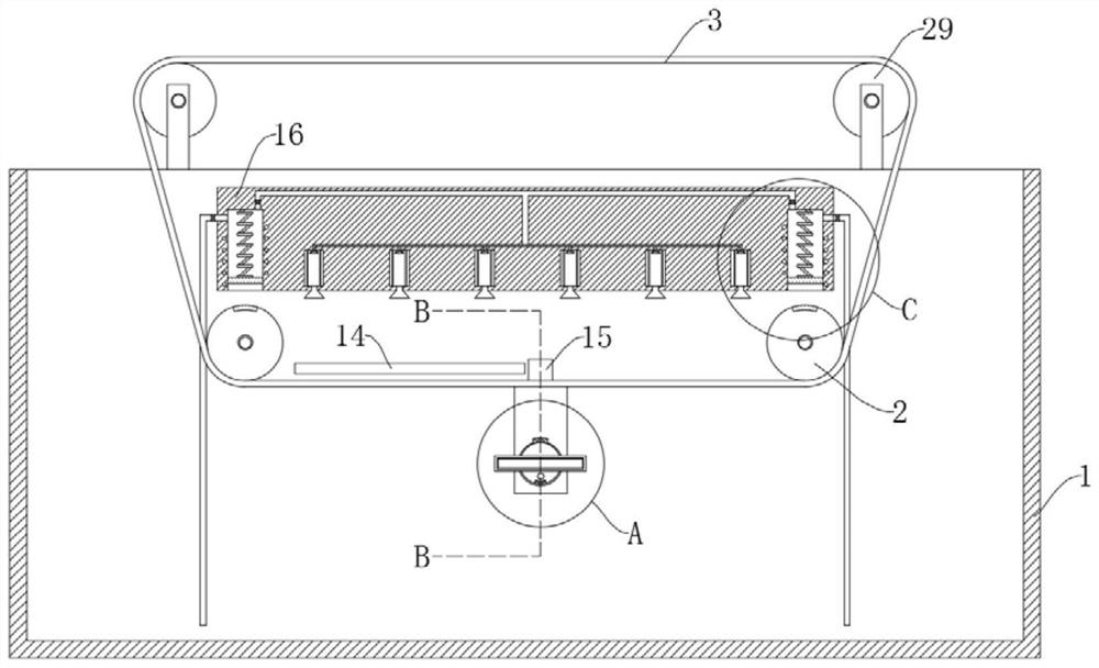
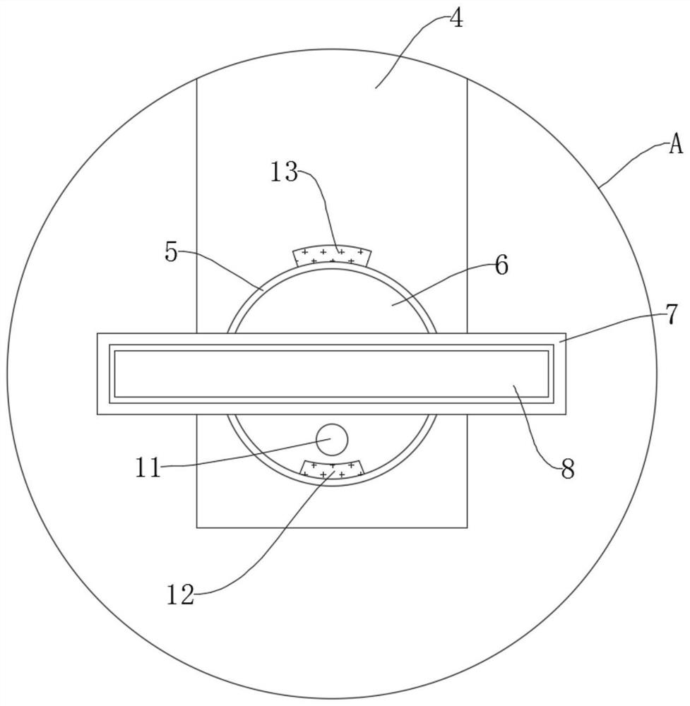
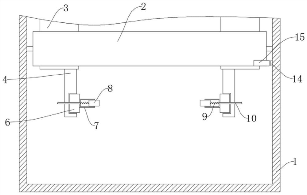
[0021] refer to Figure 1-4 , an aluminum-based circuit board etching device for LED lights, comprising a tank body 1, an etching solution is arranged in the tank body 1, two first driving rollers 2 are installed on the inner wall of the tank body 1, and two second driving rollers are installed on the upper end of the tank body 1 Two driving rollers 29, further, one of the second driving rollers 29 is connected with external driving equipment, which is prior art, two conveyor belts 3 are connected between the two first driving rollers 2 and the two second driving rollers 29 , the two conveyor belts 3 are provided with a clamping mechanism, the clamping mechanism includes a riser 4 fixedly connected to the conveyor belt 3, the side wall of the riser 4 away from the tank body 1 is provided with a circular groove 5, and the inner wall of the circular groove 5 Slidingly connected with a turntable 6, the side wall of the turntable 6 is fixedly connected with a sleeve plate 7, the i...


PUM


Abstract

The invention discloses an aluminum-based circuit board etching device for an LED lamp, which comprises a tank body, etching liquid is arranged in the tank body, two first driving rollers are arranged on the inner wall of the tank body, two second driving rollers are arranged at the upper end of the tank body, two conveying belts are connected between the two first driving rollers and the two second driving rollers, and the two conveying belts are arranged on the upper end of the tank body. And clamping mechanisms are arranged on the two conveying belts. When the conductive plate is far away from the conductive strip, the two clamping plates drive the aluminum-based circuit board to keep horizontal so as to spray and etch the upper surface of the aluminum-based circuit board, and when the conductive plate is in contact with the conductive strip, the electromagnet attracts the permanent magnet, so that the two clamping plates drive the aluminum-based circuit board to rotate for half a circle; the lower surface of the aluminum-based circuit board can be further subjected to spray etching, so that etching treatment on the two surfaces of the aluminum-based circuit board is completed, the two surfaces of the aluminum-based circuit board do not need to be etched separately, the etching treatment time is shortened, and the production speed of the aluminum-based circuit board is increased.

Description

technical field [0001] The invention relates to the technical field of LED lamp production, in particular to an aluminum-based circuit board etching device for LED lamps. Background technique [0002] As an energy-saving lamp, LED lamps have been widely used at present. When LED lamps are manufactured, they are mainly controlled through their internal aluminum-based circuit boards. At present, when producing aluminum-based circuit boards, it is necessary to An etching process is performed to form conductive traces on the aluminum-based circuit board. [0003] At present, when the aluminum-based circuit board is etched, the aluminum-based circuit board is usually moved to the etching equipment through an external conveyor belt, and then the surface of the aluminum-based circuit board is sprayed with an etching solution, but this can only be done to the aluminum-based circuit board. One side of the board is processed, and then the aluminum-based circuit board needs to be remo...

Claims


Application Information

Patent Timeline
Patent Type & Authority Applications(China)
IPC IPC(8): H05K3/00H05K3/06
CPCH05K3/002H05K3/068
Inventor 吴世谋
Owner 吴世谋
Learn More