
State feedback control method for reactive power compensation device of smart park system

A compensation device and state feedback technology, applied in reactive power compensation, reactive power adjustment/elimination/compensation, circuit devices, etc., to achieve the effects of reducing voltage flicker, suppressing system overvoltage, and suppressing harmonics

Pending Publication Date: 2022-03-25
中冶南方城市建设工程技术有限公司 +1
View PDF0 Cites 0 Cited by
  • Summary
  • Abstract
  • Description
  • Claims
  • Application Information

AI Technical Summary

Problems solved by technology

[0004] The purpose of the present invention is to provide a state feedback control method for a reactive power compensation device in a smart park system to solve the technical problem of nonlinear item processing in the physical system of the reactive power compensation device

Method used


Image

  • State feedback control method for reactive power compensation device of smart park system
  • State feedback control method for reactive power compensation device of smart park system
  • State feedback control method for reactive power compensation device of smart park system

Examples


Embodiment Construction

[0025] In order to make the objects, technical solutions, and advantages of the present disclosure, the technical solutions of the present disclosure will be clear and completely described in connection with the drawings of the present disclosure embodiments. Obviously, the described embodiment is a part of the embodiments of the present disclosure, not all of the embodiments. Based on the embodiments described herein, all other embodiments obtained without the need for creative labor without the need for creative labor.

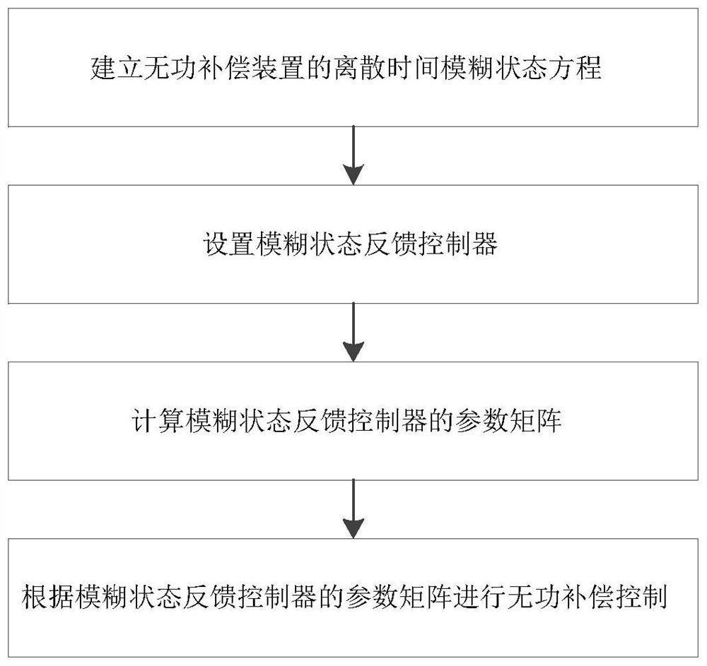
[0026] See figure 1 A state feedback control method for a smart compensation device, including the following steps:

[0027] S1, establish a discrete time blur state equation for reactive power compensation devices;

[0028] S2, set a fuzzy state feedback controller;

[0029] S3, calculate the parameter matrix of the fuzzy state feedback controller;

[0030] S4, reactive compensation control is performed according to the parameter matrix of the fuzzy state feedb...


PUM


Abstract

The invention discloses a smart park system reactive power compensation device state feedback control method. The method comprises the following steps: S1, establishing a discrete time fuzzy state equation of a reactive power compensation device; s2, setting a fuzzy state feedback controller; s3, calculating a parameter matrix of the fuzzy state feedback controller; and S4, performing reactive compensation control according to the parameter matrix of the fuzzy state feedback controller. According to the method, the technical problem of nonlinear term processing in a reactive power compensation device physical system is solved.

Description

Technical field [0001] The present invention relates to the field of reactive power compensation methods, and more particularly to a state feedback control method for unactfil compensation devices in a smart park system. Background technique [0002] The terminal users on the energy demand side of the current load-intensive urban wisdom park have gradually become energy storage, hot andotherm electronics, and loads, etc., with a variety of self-energy coordination capabilities, and when energy supply When complementary, the end user cannot meet the energy requirements of the end user, and the end user needs to respond in various forms to ensure the balance of energy supply and demand, and the typical user load modeling method for exploring the comprehensive demand response and the user responding to a variety of ways. , Enhance the user's energy use efficiency, build "Internet +" urban power grid dispatching and running an ecological service system, and supports the integrated en...

Claims


Application Information

Patent Timeline
IPC IPC(8): H02J3/18H02J3/24
CPCH02J3/18H02J3/24H02J2203/20Y02E40/30
Inventor 赵昊裔张楠李海峰
Owner 中冶南方城市建设工程技术有限公司
Learn More