
Detection equipment for electric power high-voltage equipment leakage and application thereof

A technology of high-voltage equipment and detection equipment, which is applied in the field of safety detection, can solve problems such as leak detection, inapplicable mixed gas detection, and lower detection results, and achieve the effects of improving accuracy, enhancing environmental detection adaptability, and improving cross-sensitivity

Pending Publication Date: 2022-03-25
奕瑞影像科技成都有限公司
View PDF0 Cites 0 Cited by
  • Summary
  • Abstract
  • Description
  • Claims
  • Application Information

AI Technical Summary

Problems solved by technology

Gas chromatography technology is currently mainly used for laboratory analysis and is not suitable for on-site detection. At the same time, the detection time is long in the actual operation process, and the separated substances in the subsequent analysis process may react, resulting in greatly reduced detection results.
However, electrochemical and infrared absorption spectroscopy techniques are not suitable for mixed gas detection, and there is no specific solution for SO 2 and H 2 S infrared absorption sensor
[0006] The detection technology in the above-mentioned prior art can only carry out SF 6 Leak detection, or SF only 6 The detection of one or several specific components in the decomposition products is difficult to achieve SF 6 One-stop detection of leaks and their decomposition products

Method used


Image

  • Detection equipment for electric power high-voltage equipment leakage and application thereof
  • Detection equipment for electric power high-voltage equipment leakage and application thereof
  • Detection equipment for electric power high-voltage equipment leakage and application thereof

Examples


Embodiment 1

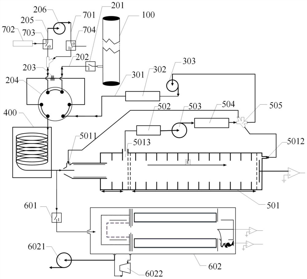
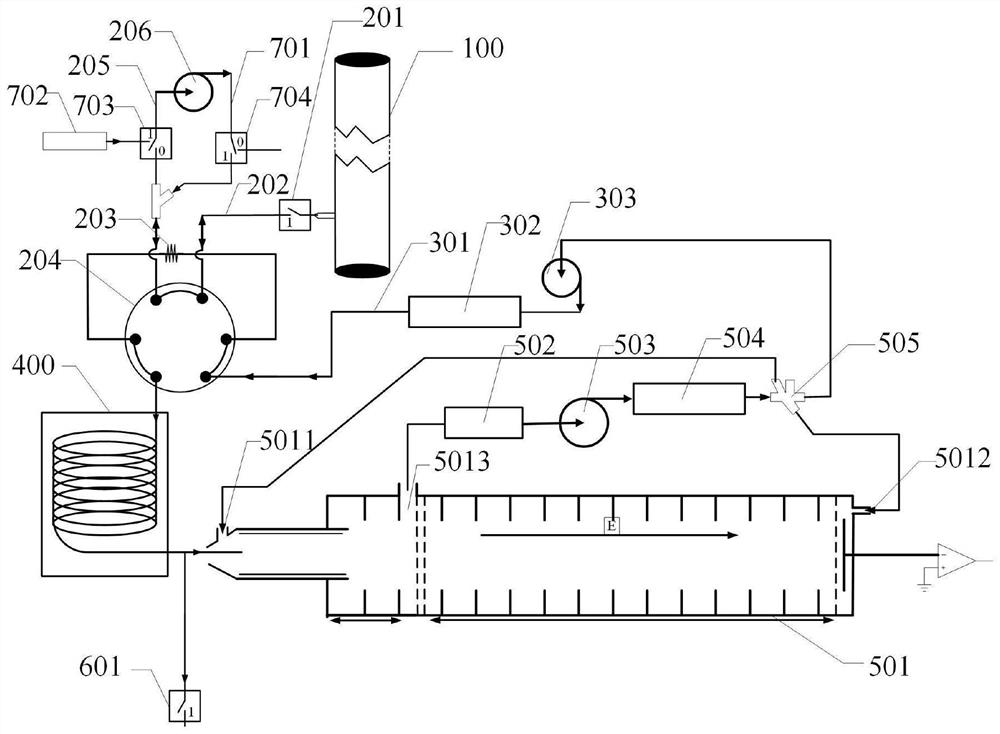
[0073] See Figure 1 ~ 3 As shown, the present embodiment provides a detection device for a power high pressure device leak, including: a sampling unit, carrier gas unit, GC column 400, and detection unit; wherein the sampling unit includes a first sampling tube sequentially connected. Road 200, quantitative ring 203, control valve 204, the second sampling line 205, and the pump 206, the input end of the first sampled line 200 is connected to the interface of the high voltage device pipe 100, and both ends of the quantitative ring 203 are both a control valve. 204 connection, one end of the control valve 204 is connected to the output of the first sample line 200, and the other end is connected to the pump 206 through the second sampling line 205, the extra gas pump 206 collects the sample in the high pressure equipment pipe 100 to the quantitative ring. In 203, the samples include sf 6 And / or sf 6 Decomposing product; Connection, for pre-separation of the mixed sample; the detec...

Embodiment 2

[0106] In this embodiment, a detecting apparatus for the leakage of a power high pressure device is provided, which is the same as that in the detection apparatus in Example 1, and details are not described herein again.

[0107] In this embodiment, the SF leakage of the electric high pressure device is allowed to use the IMS detection system separately using the IMS detection system. 6 SF 6 When the inspection or detection of the decomposing product is detected by the detection apparatus in the present embodiment, the specifically detecting method is subjected to SF in Example 1. 6Compared with the detection method of high voltage equipment or online detection, the evolution solenoid valve 601 is always in a closed state, and the pre-separated sample is all entered into the IMS detection system. Steps S1, S2, S3 are identical, This is no longer described again.

Embodiment 3

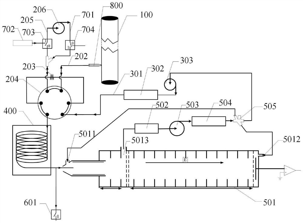
[0109] This embodiment provides a detection apparatus for the leakage of the power high pressure device, which is different from the detection device in Example 1, and the sampling solenoid valve 201 connected to the input of the first sampling line 200 Replacement is the same as the sampling structure, and the other structures are the same as in Example 1, and details are not described herein again.

[0110] As an example, the sampling structure is a sampling cone 801 or a sampled head 802; see Figure 4 , Figure 5 The sampling cone 801 is tapered, including the first port 8011 and the second port 8012, and the first port 8011 and the second port 8012 are connected to the sample cavity, and the first port 8011 is attached to the high pressure equipment pipe 100. The second port 8012 is connected to the first sampling line 200, and the inner diameter of the first port 8011 is larger than the inner diameter of the second port 8012; the sample head 802 is a pen-shaped sample head 802...


PUM


Abstract

The invention provides detection equipment for electric power high-voltage equipment leakage and application thereof.The detection equipment comprises a sampling unit, a gas carrying unit, a GC column and a detection unit, the sampling unit comprises a first sampling pipeline, a quantitative loop, a control valve, a second sampling pipeline and a sucking pump which are sequentially connected, and the gas carrying unit comprises a gas carrying pipeline, a pressure storage tank and a booster pump; the input end of the GC column is connected with the quantitative loop through a control valve, the detection unit comprises an IMS detection system and an MS detection system which are respectively connected with the output end of the GC column through a first sample introduction pipeline and a second sample introduction pipeline, and a sample introduction electromagnetic valve is arranged on the second sample introduction pipeline. According to the detection equipment, single-mode and double-mode switching of GC-IMS and MS is conveniently and quickly realized through the interface of the sampling electromagnetic valve, the environment detection adaptability of the detection equipment is enhanced, and one-stop detection on SF6 and SF6 decomposition products leaked from high-voltage equipment can be realized.

Description

Technical field [0001] The present invention belongs to the field of safety testing, and in particular, to a device for electricity high pressure equipment leakage, and its application thereof. Background technique [0002] Sf 6 (Sulfonide sulfur) has strong negative electrical, insulating and efficient arc extinguishing capabilities, is one of the most important insulation media in the current power industry, has been widely used in high pressure circuit breakers, gas insulated substations (GIS), High voltage transformer, high voltage transformer, gas insulated pipe transmission line and other high voltage equipment. With the rapid development of the national economy and the continuous improvement of people's living standards, my country's electricity industry has leap-forward development, the number of high voltage power equipment continues to increase, and SF is added in new power equipment. 6 The proportion of electrical equipment is getting bigger and larger, whereby the pow...

Claims


Application Information

Patent Timeline
IPC IPC(8): G01M3/04G01N30/02G01N30/72
CPCG01M3/04G01N30/02G01N30/72G01N2030/025
Inventor 朱伟平黄翌敏
Owner 奕瑞影像科技成都有限公司
Learn More