
Vehicle lifting device and vehicle lifting platform

A lifting device and vehicle technology, applied in the direction of lifting device, lifting frame, etc., can solve the problems of difficult positioning of vehicles, complicated control and high cost, and achieve the effects of reasonable structure design, simple control logic and space saving.

Pending Publication Date: 2022-03-25
ZHEJIANG GEELY HOLDING (GROUP) CO LTD +1
View PDF0 Cites 0 Cited by
  • Summary
  • Abstract
  • Description
  • Claims
  • Application Information

AI Technical Summary

Problems solved by technology

[0003] Most of the existing lifting devices are set on the outside of the traffic platform mechanism. When the vehicle is lifted in this scheme, it is necessary to set a lifting device at the fixed point of the vehicle body of the lifted vehicle when the vehicle is lifted. The device is controlled separately to realize the lifting of the vehicle. This solution not only takes up a large space, but also has high cost and complicated control;
[0004] In addition, there is also a lifting device to lift the tires of the vehicle to lift the vehicle, which makes it difficult to position the front and rear of the vehicle.

Method used


Image

  • Vehicle lifting device and vehicle lifting platform
  • Vehicle lifting device and vehicle lifting platform
  • Vehicle lifting device and vehicle lifting platform

Examples


Embodiment 1

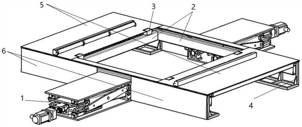
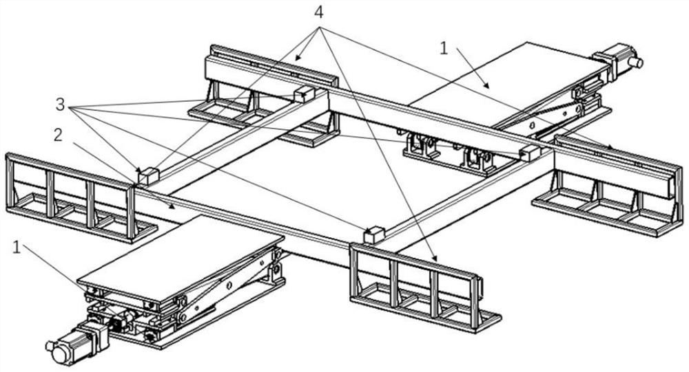
[0047] Such as Figure 1-4 As shown, the present application provides a vehicle lifting device. The vehicle lifting device includes a frame 2, at least one driving mechanism 1, at least four top braces 3, at least two driving flat plates 5 and a supporting The base 4 of the running flat 5;

[0048] Preferably, the base 4 is fixedly arranged on the ground, and the driving platform 5 is overlapped on the base 4;

[0049] Specifically, the running platform 5 can be used as a running platform of the vehicle, so as to facilitate the passage of the vehicle.

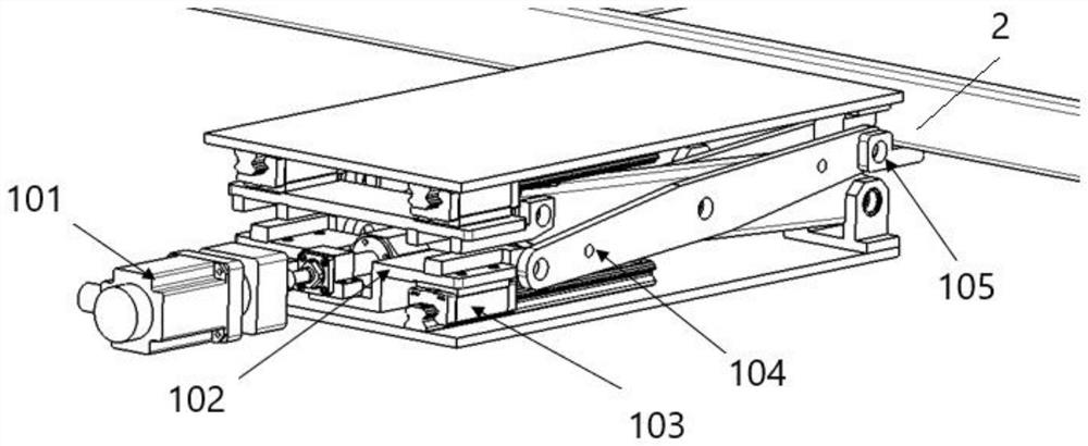
[0050] The drive mechanism 1 is fixedly connected to the frame of the frame 2; the drive mechanism 1 is used to drive the frame 2 to rise or fall;

[0051] Each of the support members 3 is fixedly arranged on the frame 2, and the support member 3 is configured to support the bottom plates on both sides of the vehicle when the frame 2 is driven up or down. support, allowing the vehicle to rise or fall;

[0052] Specifically,...

Embodiment 2

[0089] This application provides a vehicle lifting platform, such as Figure 5 As shown, it includes a first traveling platform 7, a second traveling platform 8 and a vehicle lifting device arranged between the first traveling platform 7 and the second traveling platform 8; the vehicle lifting device is the above mentioned the vehicle lifting device described above;

[0090] The first traveling platform 7, the traveling platform 5 in the vehicle lifting device and the second traveling platform 8 are in close contact to form a vehicle passage platform, wherein the vehicle passage platform is used for vehicle driving;

[0091] There is a smooth transition between the horizontal plane where the upper surface of the running platform 5 in the vehicle lifting device is located, the horizontal plane where the first running platform 7 is located, and the horizontal plane where the upper surface of the second driving platform 8 is located.

[0092] Preferably, both the first traveling...


PUM


Abstract

The invention discloses a vehicle lifting device and a vehicle lifting platform. The vehicle lifting device comprises a frame, a driving mechanism and a jacking piece. The driving mechanism is fixedly connected with a border of the frame; the driving mechanism is used for driving the frame to ascend or descend; the jacking and supporting piece is fixedly arranged on the frame, and the jacking and supporting piece is arranged to be used for jacking and supporting bottom plates on the two sides of a vehicle when the frame is driven to ascend or descend, so that the vehicle ascends or descends; according to the invention, the lifting of the vehicle can be quickly and stably realized; and the structural design is reasonable, the space is saved, and the control logic is simple.

Description

technical field [0001] The present application relates to the technical field of vehicle lifting mechanisms, in particular to a vehicle lifting device and a vehicle lifting platform. Background technique [0002] Most of the existing electric vehicle replacement stations need to lift the electric vehicle to ensure the positioning effect of the front and rear directions of the vehicle. [0003] Most of the existing lifting devices are set on the outside of the traffic platform mechanism. When the vehicle is lifted in this scheme, it is necessary to set a lifting device at the fixed point of the vehicle body of the lifted vehicle when the vehicle is lifted. The device is controlled separately to realize the lifting of the vehicle. This solution not only takes up a large space, but also has high cost and complicated control; [0004] In addition, there is also a lifting device to lift the tires of the vehicle to lift the vehicle, which makes it difficult to position the front ...

Claims


Application Information

Patent Timeline
Patent Type & Authority Applications(China)
IPC IPC(8): B66F7/06B66F7/28
CPCB66F7/065B66F7/28
Inventor 朱攀杨海东李龙杨全凯韩磊张旭
Owner ZHEJIANG GEELY HOLDING (GROUP) CO LTD
Learn More