Mechanical screw lift
A lifting device and mechanical technology, applied in the field of mechanical lifting devices, can solve the problems of small lifting stroke, inability to achieve standardization and modularization, and achieve synchronous lifting, strong lifting performance, and improved stability. Effect
- Summary
- Abstract
- Description
- Claims
- Application Information
AI Technical Summary
Problems solved by technology
Method used
Image

Examples
Embodiment approach 1
[0028] The present invention proposes a mechanical screw lifting device for lifting objects, for example, it is used in a transfer car, and is used as a lifting device of the transfer car to lift the compartment of the transfer car.
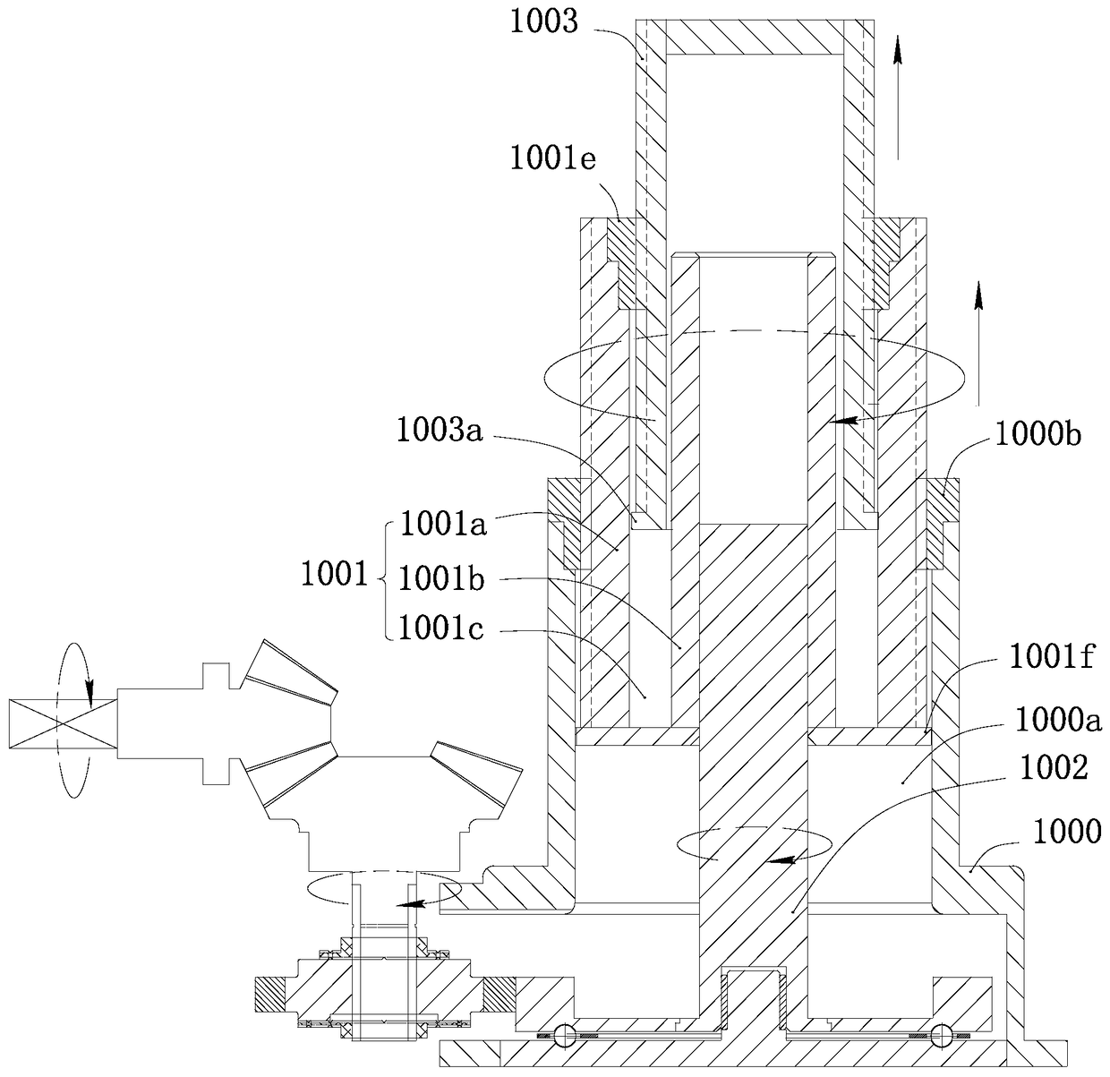
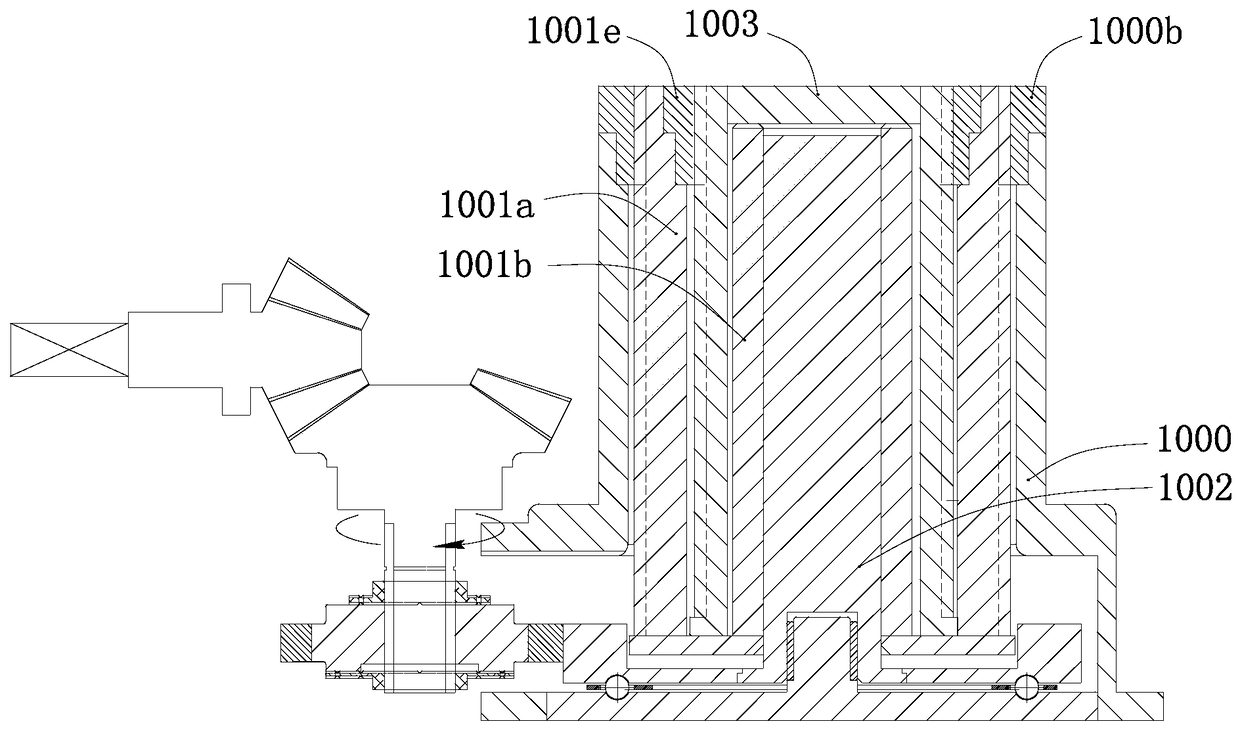
[0029] Such as figure 1 As shown, in this embodiment, each mechanical screw lifting device includes a base 1000 and a lifting part 1001 , and the lifting part 1001 is telescopically arranged on the base 1000 .
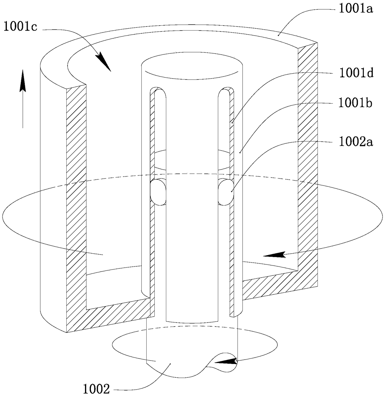
[0030] Such as Figure 1 to Figure 4 As shown, in this embodiment, the base 1000 has a cylindrical accommodating space 1000a. The inner wall of the base 1000 defining the accommodating space 1000a is provided with threads. A rotating shaft 1002 that can be driven to rotate is provided at the center of the bottom of the base 1000 . The lifting part 1001 is cylindrical, and the rotating shaft 1002 extends into the lifting part 1001 and can drive it to rotate. That is, when the lifting part 1001 rotates relative to the base 1000 , the li...
Embodiment approach 2
[0035] Such as Figure 5 and Figure 6 As shown, the present invention proposes another embodiment of the mechanical screw lifting device. In this embodiment, each mechanical screw lifting device further includes a secondary lifting part 1005 , which is cylindrical and disposed in the annular accommodating space 1001 c of the lifting part 1001 . The outer wall of the secondary lifting part 1005 is provided with a screw thread that is threadedly engaged with the inner wall of the main body 1001a of the lifting part 1001 . Moreover, the inner wall of the secondary lifting part 1005 is provided with threads opposite to the thread direction of its outer wall, and a second end lifting part 1003' is arranged inside it, and the outer wall of the second end lifting part 1003' is provided with the secondary lifting part 1003'. The screw thread of the inner wall of the lifting part 1005 fits.
[0036] In addition, the number of secondary lifting parts 1005 in this embodiment is not u...
Embodiment approach 3
[0039] Such as Figure 7 As shown, another embodiment of the mechanical screw lifting device proposed by the present invention, its main structure is basically the same as the above embodiment. However, in this embodiment, the lifting part 1001 includes a main body 1001g and a rotating shaft sleeve 1001h fixed on the bottom of the main body 1001g, the rotating shaft 1002 is provided with threads, and the inner wall of the rotating shaft sleeve 1001h is provided with matching threads, and the rotating shaft 1002 passes through The rotating shaft sleeve 1001h has a stop portion 1002c fixed on its upper end. Specifically, in this embodiment, the structure of the rotating shaft sleeve 1001h can be realized in various ways, for example, a nut is used to fix the bottom end of the body 1001g, and the nut is screwed into the rotating shaft 1002 . When the rotating shaft 1002 rotates, the lifting part 1001 can be lifted upwards by relying on the screw fitting structure between the lif...
PUM
 Abstract
Description
Claims
Application Information
 - R&D
- Intellectual Property
- Life Sciences
- Materials
- Tech Scout
- Unparalleled Data Quality
- Higher Quality Content
- 60% Fewer Hallucinations
Browse by: Latest US Patents, China's latest patents, Technical Efficacy Thesaurus, Application Domain, Technology Topic, Popular Technical Reports.
© 2025 PatSnap. All rights reserved.Legal|Privacy policy|Modern Slavery Act Transparency Statement|Sitemap|About US| Contact US: help@patsnap.com