Variable-thickness laying layer parameterization design method for continuous fiber reinforced composite part

A reinforced composite material and continuous fiber technology, which is applied in the field of continuous fiber reinforced composite material parts, can solve problems such as the inability to comprehensively consider interaction effects, reduced calculation efficiency, and increased optimization iteration time, so as to improve lightweight effects, reduce material costs, The effect of improving design efficiency

Pending Publication Date: 2022-03-25
JILIN UNIV
View PDF10 Cites 0 Cited by
  • Summary
  • Abstract
  • Description
  • Claims
  • Application Information

AI Technical Summary

Problems solved by technology

Due to the high dimensionality and different forms of variable-thickness layup design variables, it is difficult to automatically update the layup design variables of parts in different optimization tasks during structural optimization design without parametric design of variable-thickness layups. Iteration can only manually modify the layup design of a part according to the optimization calculation result of a certain optimization task, and substitute the revised layup design scheme into the structural model, and then perform the analysis and calculation of the next optimization task, resulting in optimization iteration time The calculation efficiency is significantly reduced, and the interaction effect of each design variable on the structural performance cannot be considered comprehensively.

Method used


Image

  • Variable-thickness laying layer parameterization design method for continuous fiber reinforced composite part
  • Variable-thickness laying layer parameterization design method for continuous fiber reinforced composite part
  • Variable-thickness laying layer parameterization design method for continuous fiber reinforced composite part

Examples


Embodiment

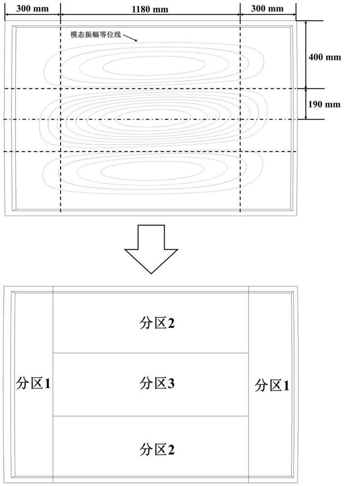
[0045] (1) Firstly, according to the load deformation characteristics and performance requirements of the roof panel, the number and position relationship of the variable-thickness laminate partitions of the parts are planned. The roof panel has a large area and low stiffness, and its main low-order constrained modal characteristics have an important impact on the vehicle interior vibration and noise (NVH) performance. Therefore, the design requirement of the roof panel is to constrain the roof panel weight by changing The thickness ply design maximizes the stiffness of the roof panel and minimizes the amplitude of the first-order constrained mode. Therefore, in this implementation case, the low-order constrained modal analysis of the roof panel should be carried out first. According to the connection constraint state of the roof panel with the side wall and the front and rear windshields in the working condition, the first-order elastic mode is calculated by constraining the ...


PUM

PropertyMeasurementUnit
thicknessaaaaaaaaaa
thicknessaaaaaaaaaa
thicknessaaaaaaaaaa

Abstract

The invention discloses a continuous fiber reinforced composite part variable-thickness laying layer parameterization design method. The method comprises the steps that laying layer partitions are planned according to the loaded deformation characteristic of a part to be laid layer in the use working condition; determining an endpoint position parameter l of the partition boundary line and a shape parameter v of the partition boundary line; determining a layer quantity parameter n of each subarea according to the layer thickness of each subarea; determining a local shared laying layer partition parameter R of each laying layer; wherein the local shared paving layer partition parameter R is the situation that continuous paving layers can cover partitions at the same time; the laying angle theta of the shared laying layer is determined; wherein theta is equal to 0 degree, 45 degrees,-45 degrees or 90 degrees; and a continuous fiber reinforced composite material is adopted, and the part to be laid is laid according to the endpoint position parameter l, the shape parameter v, the laying number parameter n, the partition parameter R and the laying angle theta.

Description

technical field [0001] The invention belongs to the technical field of continuous fiber-reinforced composite material parts, in particular to a parameterized design method for variable-thickness layup of continuous fiber-reinforced composite material parts. Background technique [0002] Fiber-reinforced composite materials have high specific strength, high specific stiffness, and good impact resistance and energy absorption. With the rapid development of carbon fiber, glass fiber and basalt fiber materials, the cost continues to decrease, and the development of rapid prototyping technology for fiber-reinforced composite materials, the application of fiber-reinforced composite materials in engineering fields such as automobiles, aerospace, wind power and sporting goods is increasing. more extensive. In particular, the application prospects of continuous fiber reinforced composite materials are broader. In order to fully utilize the designability of continuous fiber reinforce...

Claims


Application Information

Patent Timeline
Patent Type & Authority Applications(China)
IPC IPC(8): B29C70/30B29C70/54
CPCB29C70/30B29C70/54
Inventor 王登峰吕天佟
Owner JILIN UNIV
Why Eureka
Try Eureka