
Automatic clamping equipment for metal product machining

A metal product, automatic technology, used in metal processing equipment, metal processing machine parts, manufacturing tools, etc., can solve the problem of unadjustable clamping force

Active Publication Date: 2022-03-25
沭阳天勤工具有限公司
View PDF7 Cites 2 Cited by
  • Summary
  • Abstract
  • Description
  • Claims
  • Application Information

AI Technical Summary

Problems solved by technology

[0003] The invention provides an automatic clamping device for metal product processing to solve the problem that the existing clamping force cannot be adjusted

Method used


Image

  • Automatic clamping equipment for metal product machining
  • Automatic clamping equipment for metal product machining
  • Automatic clamping equipment for metal product machining

Examples


Embodiment Construction

[0023] The following will clearly and completely describe the technical solutions in the embodiments of the present invention with reference to the accompanying drawings in the embodiments of the present invention. Obviously, the described embodiments are only some, not all, embodiments of the present invention. Based on the embodiments of the present invention, all other embodiments obtained by persons of ordinary skill in the art without making creative efforts belong to the protection scope of the present invention.

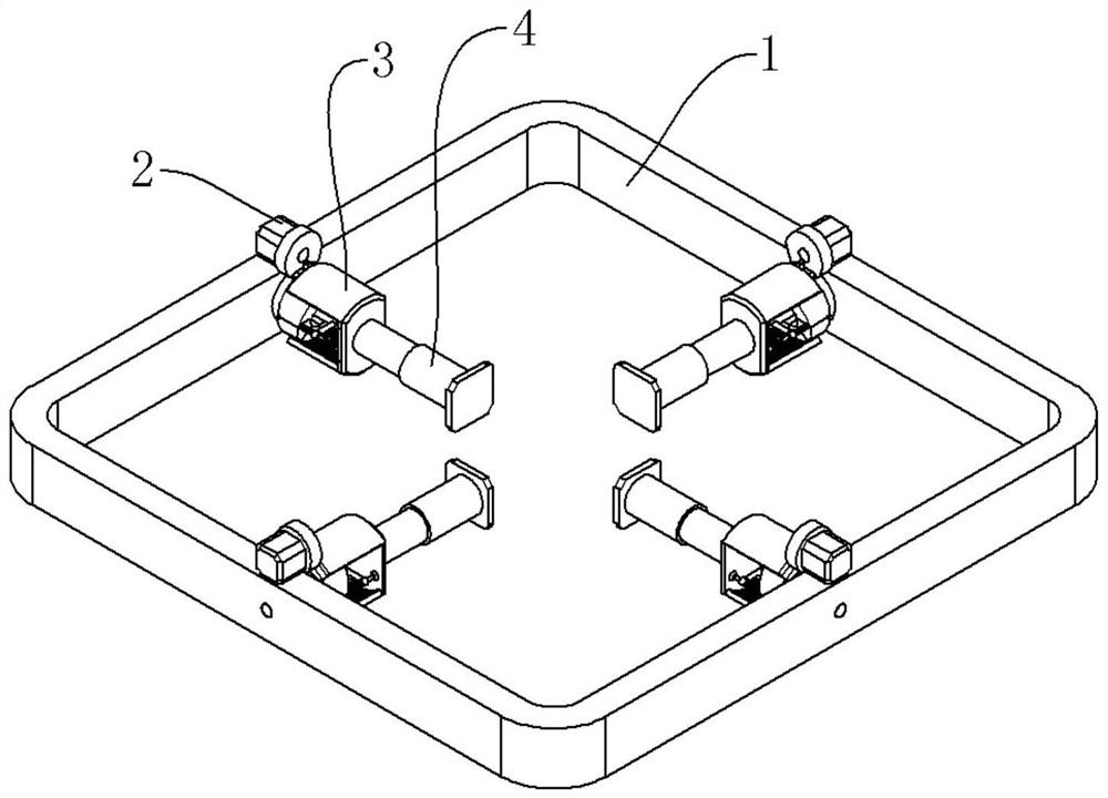
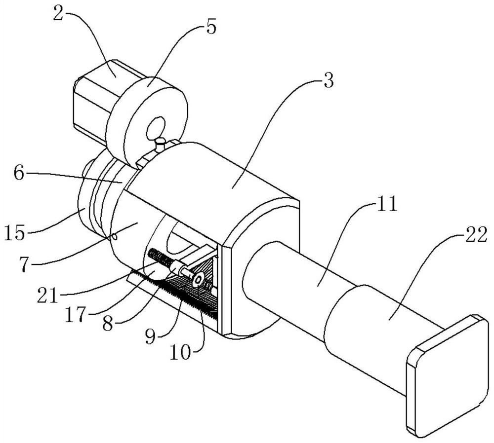
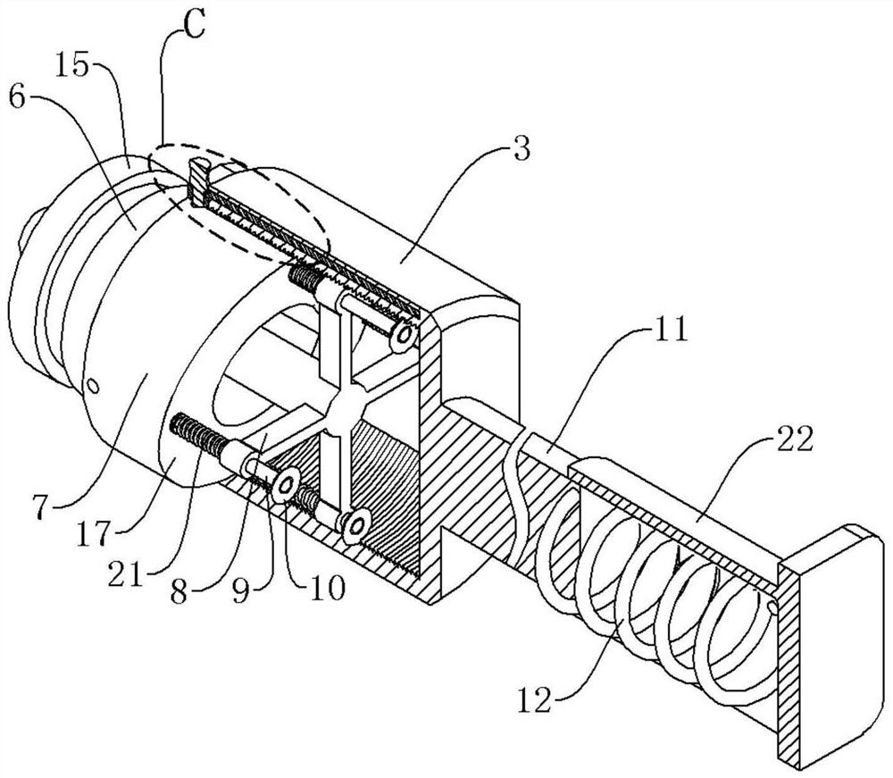
[0024] An embodiment of an automatic clamping device for metal product processing of the present invention, such as Figure 1 to Figure 7 As shown, an automatic clamping device for metal product processing includes a fixed frame 1, a plurality of driving assemblies, a plurality of clamping assemblies and a plurality of pushing assemblies. The fixed frame 1 is arranged horizontally, and the fixed frame 1 has a square frame structure. An installation hole is pr...


PUM


Abstract

The invention relates to the field of metal product machining, in particular to automatic clamping equipment for metal product machining. A mounting hole is formed in the middle of each edge of the fixing frame. The driven gear is rotatably installed on the inner wall of the fixing frame, and the motor drives the driven gear to rotate through the transmission mechanism. The propelling column is fixedly connected with the driven gear, and the inner end face of the propelling column is an inclined face. The transmission arc plates are slidably mounted on the propelling column in the axial direction, a plurality of mounting positions of the transmission arc plates are arranged on the propelling column, and the two transmission arc plates are symmetrically arranged on the propelling column. The inner and outer ends of the fixing rod extend out of the inner end of the pushing column. Each pushing rod is installed on one rod of the fixing frame in a sliding mode in the axial direction of the pushing column, and the inner end of each pushing rod makes contact with the inclined face of the pushing column so that the transmission arc plates can be pushed to move inwards when the pushing rods move inwards. And the pushing spring is sleeved on the pushing rod and is positioned between the shaft shoulder and the fixing frame. And the position of the transmission arc plate on the pushing column is adjusted, so that the effect of adjusting the clamping force is achieved.

Description

technical field [0001] The invention relates to the field of metal product processing, in particular to an automatic clamping device for metal product processing. Background technique [0002] During the processing of metal products, clamping equipment is often required to handle various parts of metal products. The clamping equipment can not only improve work efficiency, but also save labor costs. The precision requirements of various parts of metal products are different. For some parts with high precision requirements and low quality, the required clamping force is often small. For some components with lower precision requirements and higher mass, the required clamping force is often greater. The existing clamping device often can only adopt one kind of clamping force, so it can only clamp a single component, and the scope of application is small. Contents of the invention [0003] The invention provides an automatic clamping device for processing metal products to so...

Claims


Application Information

Patent Timeline
Patent Type & Authority Applications(China)
IPC IPC(8): B23Q3/06
CPCB23Q3/062
Inventor 黄贤明
Owner 沭阳天勤工具有限公司
Learn More