A kind of carbon fiber composite material and its preparation system and preparation method
A composite material and preparation system technology, applied in the field of carbon fiber composite materials and its preparation system and preparation, can solve problems such as unsuitable carbon fiber composite materials, clogging of printer nozzles, and deformation of printed objects
- Summary
- Abstract
- Description
- Claims
- Application Information
AI Technical Summary
Problems solved by technology
Method used
Image
Examples
specific Embodiment approach 1
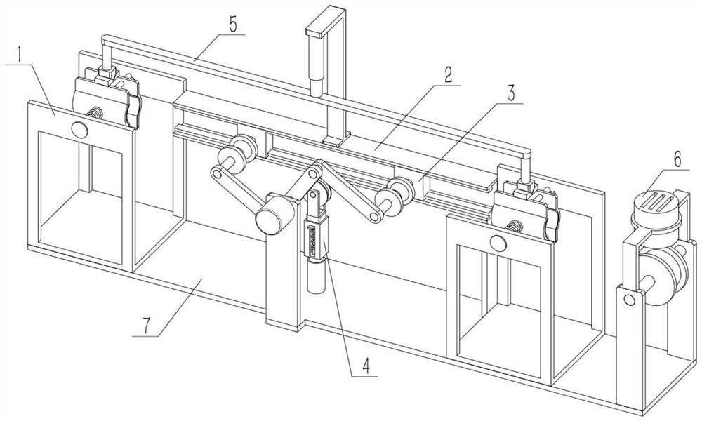
[0033] Such as Figure 1-8 As shown, a carbon fiber composite material preparation system includes an off-stop mechanism 1, a stand 2, a supporting mechanism 3, a tester 4, a synchronization mechanism 5, a tail sequence mechanism 6 and a base 7, and the off-stop mechanism 1 is mirror-symmetrical There are two, the two off-stop mechanisms 1 are respectively fixed on the left and right sides of the base 7, the stand 2 is fixed on the front side of the base 7, the stand 2 is located between the two off-stop mechanisms 1, and the supporting mechanism 3 is slidingly connected to the stand 2, the supporting mechanism 3 is fixed on the base 7, the tester 4 is fixed on the base 7, the tester 4 is located directly in front of the tester 4, and the synchronization mechanism 5 is fixed on the stand 2 Above, the left and right ends of the lower end of the synchronization mechanism 5 are in contact with the upper ends of the two off-stop mechanisms 1 respectively.
specific Embodiment approach 2
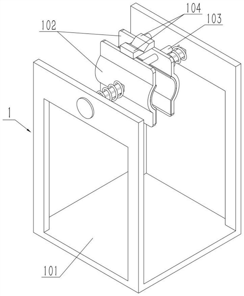
[0035] Such as Figure 1-8 As shown, the off-stop mechanism 1 includes a mechanism frame 101, a clip adapter 102, a guide rod 103 and a track block 104. The front and rear ends of the upper end of the mechanism frame 101 are slidably connected to a clip adapter 102, and the clip adapter 102 located at the rear side Two guide rods 103 are affixed to the front end of the upper side of the device 102, and the clip adapter 102 located on the front side is slidably connected to the two guide rods 103, and a track block 104 is fixed on the two clip adapters 102, and the two tracks The blocks 104 are arranged mirror-symmetrically, and the inner sides of the two track blocks 104 are inclined downward. The distance between the two clamps 102 can be adjusted through elasticity, and the carbon fiber composite material can be clamped to a certain extent through its automatic reset, which is convenient for the material to be installed in various positions.
specific Embodiment approach 3
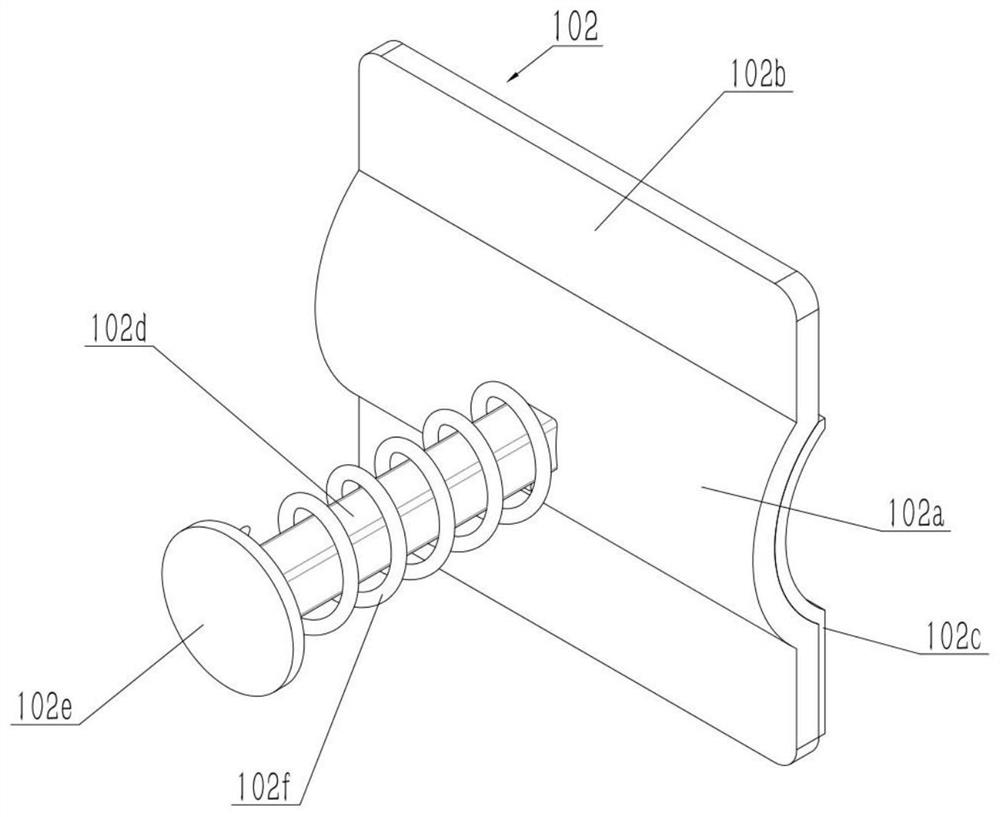
[0037] Such as Figure 1-8 As shown, the clamp adapter 102 includes an arc portion 102a, a vertical extension portion 102b, a sponge 102c, a sliding rod 102d, a contact portion 102e and a compression spring I102f, and the upper and lower ends of the arc portion 102a are fixedly connected to a vertical extension portion 102b, The sponge 102c is affixed to the inner end of the arc portion 102a, the sliding rod 102d is affixed to the outer end of the arc portion 102a, the contact portion 102e is affixed to the outer end of the sliding rod 102d, the compression spring I102f is sleeved on the sliding rod 102d, and the compression spring The outer end of I102f is in contact with the disengagement mechanism 1, and the slide bar 102d is slidingly connected with the disengagement mechanism 1. The sponge 102c plays a certain role in protecting the carbon fiber composite material. The carbon fiber composite material is fixed to a certain extent by using the two arc portions 102a, and th...
PUM
 Abstract
Description
Claims
Application Information
 - R&D
- Intellectual Property
- Life Sciences
- Materials
- Tech Scout
- Unparalleled Data Quality
- Higher Quality Content
- 60% Fewer Hallucinations
Browse by: Latest US Patents, China's latest patents, Technical Efficacy Thesaurus, Application Domain, Technology Topic, Popular Technical Reports.
© 2025 PatSnap. All rights reserved.Legal|Privacy policy|Modern Slavery Act Transparency Statement|Sitemap|About US| Contact US: help@patsnap.com


