
Laser cutting nozzle

A laser cutting and nozzle technology, applied in laser welding equipment, welding equipment, metal processing equipment, etc., can solve the problems of large loss of protective lenses, oxygen concentration drop, oxygen concentration drop, etc., to improve the inconsistency of the four sides of the cutting, and to compensate for the oxygen concentration The attenuation and the effect of avoiding a sharp drop in oxygen concentration

Pending Publication Date: 2022-03-25
上海波刺自动化科技有限公司
View PDF0 Cites 0 Cited by
  • Summary
  • Abstract
  • Description
  • Claims
  • Application Information

AI Technical Summary

Problems solved by technology

[0002] When cutting plates with laser oxygen, when the height of the nozzle from the surface of the plate (following height) increases, the entrainment of the ambient airflow on both sides of the slit will increase, resulting in a decrease in oxygen concentration, resulting in impermeable cutting
The existing process cannot achieve the purpose of compensating the oxygen concentration by adjusting parameters such as air pressure and focus, so laser oxygen plate cutting with low follow-up height is often used, but low follow-up cutting has problems such as large nozzle loss and large loss of protective lenses.
Moreover, when the existing nozzle cuts the plate, there are differences in the entrainment of the ambient airflow on both sides of the slit, resulting in differences in the oxygen concentration on both sides of the slit, resulting in the phenomenon that the four sides of the cut are inconsistent
In addition, when the thickness of the cutting plate increases, the required kerf width increases. When the plate thickness increases to a certain extent, the increase in plate thickness and the expansion of the kerf will lead to a sharp drop in oxygen concentration, resulting in impermeable cutting

Method used


Image

  • Laser cutting nozzle
  • Laser cutting nozzle
  • Laser cutting nozzle

Examples


Embodiment Construction

[0026] The present invention will be further described in detail below in conjunction with the accompanying drawings and embodiments. It should be understood that the specific embodiments described here are only used to explain the present invention, but not to limit the present invention. In addition, it should be noted that, for the convenience of description, only some structures related to the present invention are shown in the drawings but not all structures.

[0027] In the description of the present invention, unless otherwise clearly specified and limited, the terms "connected", "connected" and "fixed" should be understood in a broad sense, for example, it can be a fixed connection, a detachable connection, or an integrated ; It can be a mechanical connection or an electrical connection; it can be a direct connection or an indirect connection through an intermediary, and it can be the internal communication of two components or the interaction relationship between two ...


PUM


Abstract

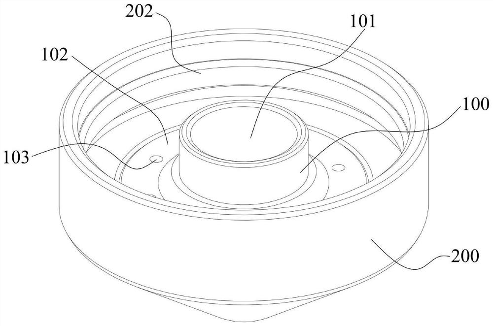
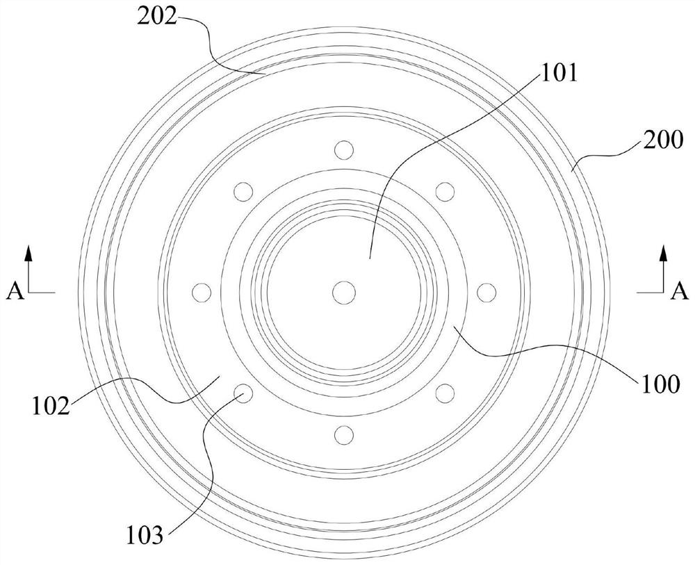
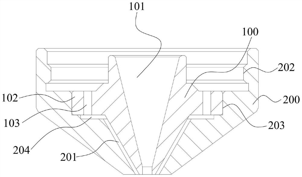
The invention belongs to the technical field of laser cutting, and discloses a laser cutting nozzle which comprises a nozzle inner sleeve and a nozzle outer sleeve, a first air channel is formed in the center of the nozzle inner sleeve in the axial direction, the first air channel is configured to convey cutting gas, and the nozzle inner sleeve is sleeved with the nozzle outer sleeve; a second air channel is formed between the inner wall of the nozzle outer sleeve and the outer wall of the nozzle inner sleeve and is configured to convey compensation gas, an annular gas opening is formed in the gas outlet end of the second air channel, and a threaded structure is arranged at the end, away from the nozzle inner sleeve, of the inner wall of the nozzle outer sleeve and is in threaded connection with the laser head. According to the laser cutting nozzle, attenuation of oxygen concentration at a cutting seam can be compensated, high follow-up cutting is achieved, and the phenomena that four cutting edges are inconsistent and thick plates cannot be cut thoroughly can be improved.

Description

technical field [0001] The invention relates to the technical field of laser cutting, in particular to a laser cutting nozzle. Background technique [0002] When cutting plates with laser oxygen, when the height of the nozzle from the surface of the plate (following height) increases, it will cause the entrainment of the ambient airflow on both sides of the slit to intensify, resulting in a decrease in the oxygen concentration, resulting in impermeable cutting. The existing technology cannot achieve the purpose of compensating oxygen concentration by adjusting parameters such as air pressure and focus. Therefore, laser oxygen plate cutting with low follow-up height is often used, but low follow-up cutting has problems such as large nozzle loss and large loss of protective lenses. Moreover, when the existing nozzle cuts the plate, there are differences in the entrainment of the ambient airflow on both sides of the slit, resulting in differences in the oxygen concentration on ...

Claims


Application Information

Patent Timeline
IPC IPC(8): B23K26/38B23K26/70B23K26/12
CPCB23K26/38B23K26/702B23K26/123
Inventor 唐晔陈明洁
Owner 上海波刺自动化科技有限公司
Learn More