Tubular pile sinking test device

A test device and pile sinking technology, which is applied in the test of foundation structure, sheet pile wall, building, etc., can solve the problems that the pile foundation deviates from the vertical direction, cannot ensure the seamless contact of the observation window of the model pile, and the test results are inaccurate, etc. , to achieve the effect of ensuring consistency

Pending Publication Date: 2022-03-22
SHANDONG ELECTRIC POWER ENG CONSULTING INST CORP
View PDF5 Cites 1 Cited by
  • Summary
  • Abstract
  • Description
  • Claims
  • Application Information

AI Technical Summary

Benefits of technology

This patented testing apparatus connects to an enclosed system where it cannot move freely when wrapped around by another object or underground. It uses a limited movement control mechanism attached outside its bottom edge for controlling how far one end of this controlled mechanism moves towards other ends while keeping them within certain limits. By allowing these movements inside the machine, there are no impact on the accuracy of the tested models' interfaces due to changes caused by water level fluctuations. Additionally, the use of a fixed structure allows for flexible placement and real-time adjustment of the simulation conditions without interferring with previous tests results.

Problems solved by technology

This patents describes different methods for measuring stress concentration at specific locations along pipes made up of prestack strengthened concrete plugs called pristoncastings. These measurements help predict how much force will act upon them over time without causing damage. They were developed beforehand through experiments conducted under controlled conditions such as water pressure or temperature. There was no technical problem addressed earlier but it could lead to incorrect conclusions about the behavior of these materials near areas where they may actually work well.

Method used


Image

  • Tubular pile sinking test device
  • Tubular pile sinking test device

Examples


Embodiment 1

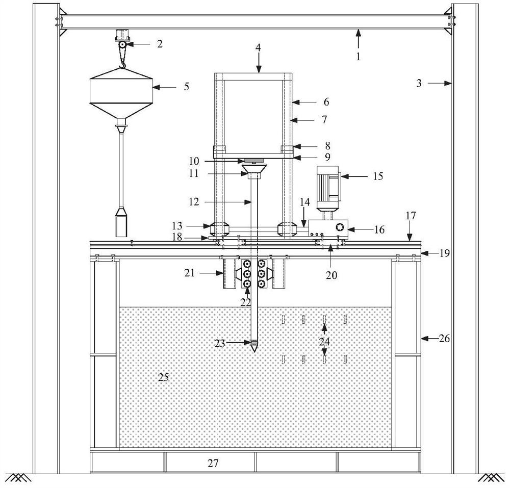
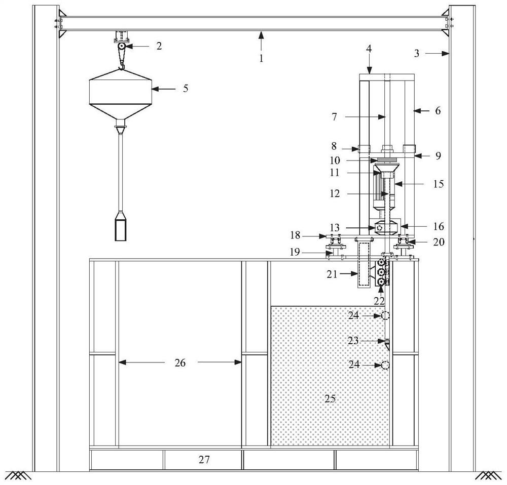
[0027] A pile sinking test device for pipe piles, including a model tank for holding sand samples. In this embodiment, the model tank adopts a cubic structure with an open top, including four side tank walls 26, and four side tank walls. The wall of the tank is fixed on the base 27 by bolts.

[0028] In order to realize the visualization of the pile sinking test, in this embodiment, the side wall of the model tank is made of transparent tempered glass.

[0029] In one embodiment, according to actual needs, the length, width, and height of the model groove are 1.5m, 1.5m, and 1.2m respectively, and the thickness of the transparent tempered glass is 19mm. It can be understood that it can be set according to actual needs. Dimensions of the model slot and its side slot walls.

[0030] The top of the model groove is provided with a support member, and a vertical displacement drive mechanism for driving the model pile to move vertically is installed on the support member. The verti...


PUM


Abstract

The invention relates to a pile sinking test device for a tubular pile. The pile sinking test device comprises a model tank and a pile sinking device, the supporting piece is installed at the top of the model groove, the supporting piece is provided with a vertical displacement driving mechanism, and the vertical displacement driving mechanism can be fixedly connected with the model pile; the limiting mechanism comprises at least three sets of limiting pieces installed on the supporting piece, the limiting pieces and the groove wall of the model groove can form a space allowing the model pile to penetrate through, and the limiting pieces can make contact with the outer side face of the model pile and jointly act with the groove wall of the model groove to limit the model pile from moving in the vertical direction; by adopting the test device, the accuracy of a test result can be ensured.

Description


Claims


Application Information

Patent Timeline
Owner SHANDONG ELECTRIC POWER ENG CONSULTING INST CORP
Why Eureka
Try Eureka