
Elevator traction machine safety detection device and elevator control equipment

An elevator traction machine and safety detection technology, which is applied to elevators, lifts, transportation and packaging in buildings, etc., can solve problems such as safety accidents, traction machine deviation from the installation position, and increased swing and jump of elevator traction ropes , to achieve the effect of ensuring safety

Pending Publication Date: 2022-03-22
IFE ELEVATORS
View PDF0 Cites 0 Cited by
  • Summary
  • Abstract
  • Description
  • Claims
  • Application Information

AI Technical Summary

Problems solved by technology

[0002] During the operation of the elevator, the elevator traction machine is tilted due to external reasons (such as elevator overload operation, resonance, failure of the shock absorber, earthquake, etc.), which will cause a certain displacement of the traction machine, and the traction sheave If the tilt occurs, the swing or jump of the elevator traction rope will increase, which will cause resonance in the car and cause poor experience for passengers on the elevator. If it is heavy, the traction machine will seriously deviate from the installation position, and the swing or jump of the elevator traction rope will be too large. Interference between components occurs during operation, which eventually leads to safety accidents
At present, the general design scheme for the traction device of passenger elevators is to add a shock absorber (such as shock-absorbing rubber) at the traction machine. There is no safety detection device for an elevator traction machine, which greatly affects the elevator. security of operation

Method used


Image

  • Elevator traction machine safety detection device and elevator control equipment
  • Elevator traction machine safety detection device and elevator control equipment
  • Elevator traction machine safety detection device and elevator control equipment

Examples


Embodiment Construction

[0029] In order to describe the technical content, structural features, achieved objects and effects of the present invention in detail, the following detailed description is given in conjunction with the embodiments and the accompanying drawings.

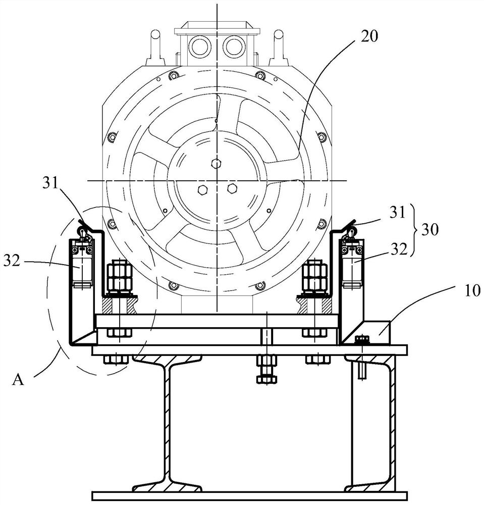
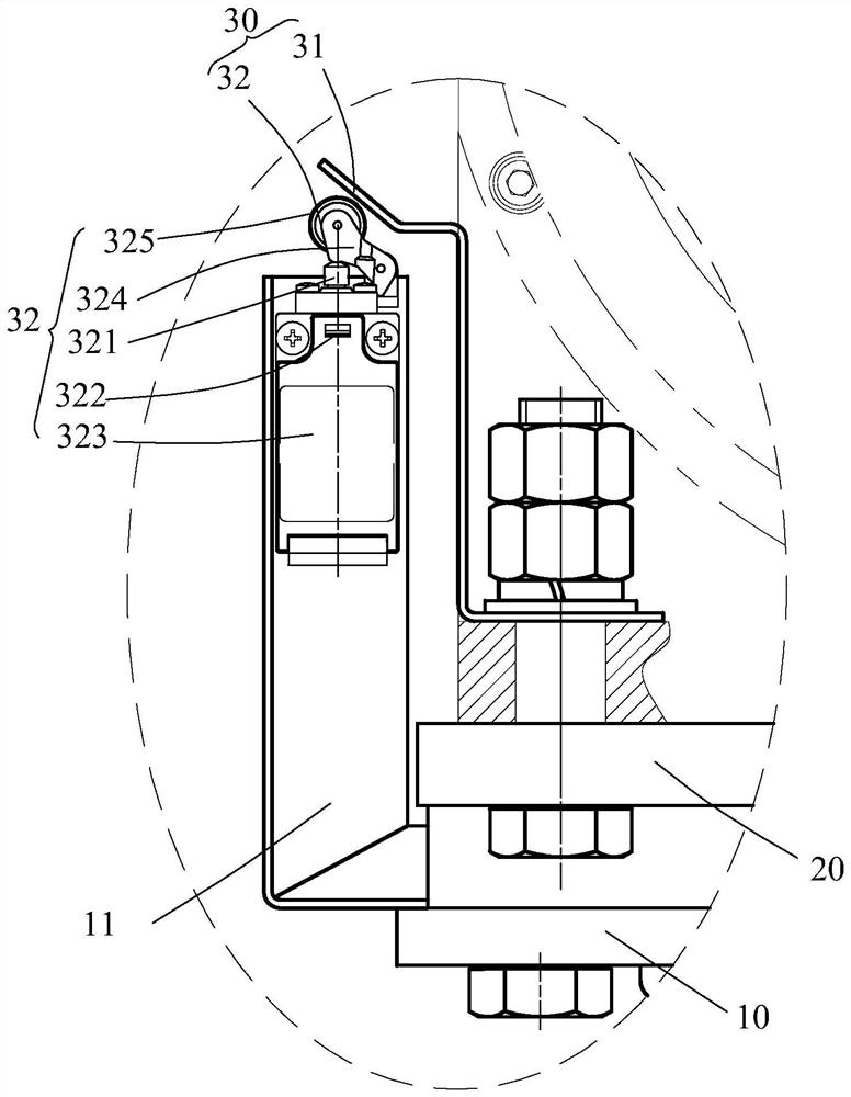
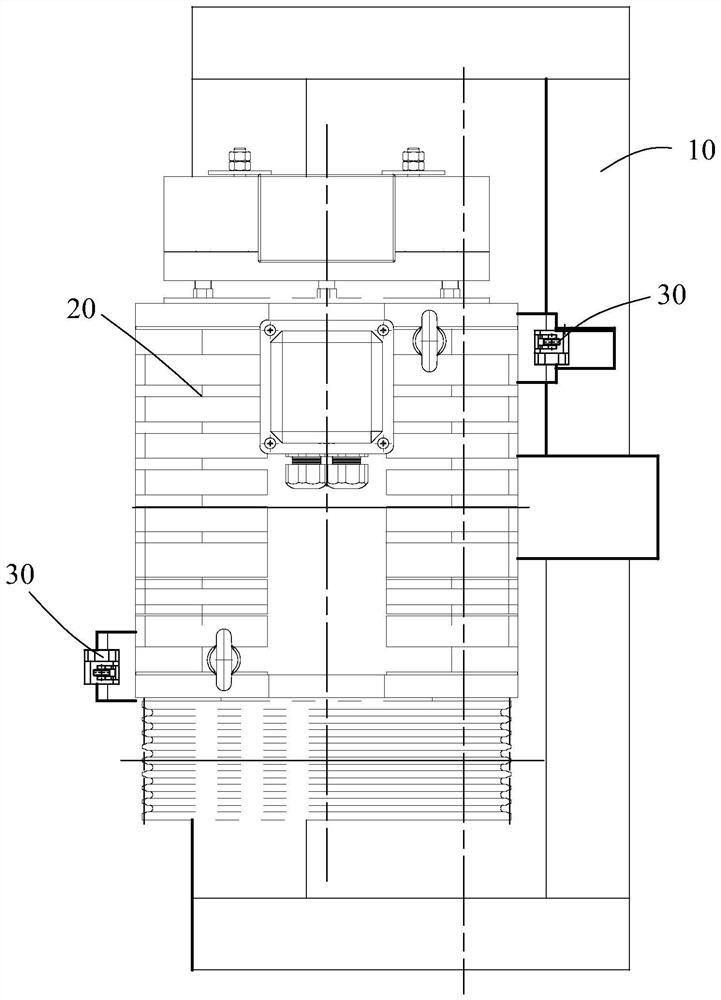
[0030] refer to figure 1 and figure 2 , the present invention discloses an elevator control device. The traction machine 20 is installed on a frame 10. The elevator control device includes a detection device and a main control machine. The detection device outputs a fault when the traction machine 20 tilts or swings. signal, the main control computer controls the elevator to stop running according to the fault signal.

[0031] refer to figure 1 and figure 2 , the detection device includes a plurality of trigger units 30 and detection circuits, each trigger unit 30 includes a switch plate 31 installed on the traction machine 20 and a detection switch 32 installed on the frame 10, the switch plate 31 and the detection switch 32...


PUM


Abstract

The invention discloses an elevator traction machine safety detection device and a traction machine control device.A traction machine is installed on a rack, the detection device comprises a plurality of trigger units and a detection circuit, and the multiple trigger units are arranged on the different sides and / or the same side of the traction machine at certain intervals; each trigger unit comprises a switch beating plate installed on one of the traction machine and the rack and a detection switch installed on the other of the traction machine and the rack, and the switch beating plate and the detection switch are oppositely arranged at a preset interval in the tiltable direction of the traction machine. The traction machine inclines or swings to enable the switch beating plate to move relative to the detection switch so as to trigger the detection switch, and the detection circuit is connected with the detection switch and outputs a fault signal when the detection switch acts. Compared with the prior art, when the traction machine swings due to inclination or vibration, the switch beating plate can be driven to trigger the detection switch so as to generate a fault signal, and the running safety of an elevator is ensured.

Description

technical field [0001] The invention relates to the field of elevators, in particular to an elevator traction machine safety detection device and elevator control equipment. Background technique [0002] During the operation of the elevator, the elevator traction machine is tilted due to external reasons (such as elevator overload operation, resonance, failure of the shock absorber, earthquake, etc.), which may cause a certain displacement of the traction machine, and the traction sheave If the tilt occurs, the swing or jump of the elevator traction rope will increase, resulting in resonance in the car and poor passenger ride experience. If it is serious, the traction machine will seriously deviate from the installation position, the swing or jump of the elevator traction rope will be too large, and the elevator will be damaged. Interference between components occurs during operation, which eventually leads to safety accidents. At present, the general design scheme for the ...

Claims


Application Information

Patent Timeline
Patent Type & Authority Applications(China)
IPC IPC(8): B66B5/02B66B11/08
CPCB66B5/02B66B11/008
Inventor 李杰覃海才
Owner IFE ELEVATORS
Learn More