
Monitoring system and method for forming grouting pipeline

A monitoring system and grouting pipe technology, applied in ceramic molding machines, auxiliary molding equipment, supply devices, etc., can solve the problems of green body air bubbles, pipeline lack of grouting, grouting time deviation, etc., to reduce variation and overlap. the probability of, and the effect of reducing the generation of forming bubbles

Active Publication Date: 2022-03-22
LIXIL AS SANITARY MFG (SHANGHAI) CO LTD
View PDF5 Cites 0 Cited by
  • Summary
  • Abstract
  • Description
  • Claims
  • Application Information

AI Technical Summary

Problems solved by technology

In order to improve production efficiency in the above process, multiple molding production lines are often set up in the factory, and grouting is performed by one grouting pipeline. If the number of pulp forming production lines is greater than 2, the pipeline will lack pulp, which will cause air bubbles in the green body
[0003] Although the number of molding production lines for grouting at the same time can be stipulated in the form of shift scheduling, but in actual production, it is often impossible to effectively implement it due to negligence or shortening the working hours of the operators.
Moreover, the deviation between the actual grouting time and the scheduled grouting time cannot be effectively monitored

Method used


Image

  • Monitoring system and method for forming grouting pipeline

Examples


Embodiment Construction

[0022] Below in conjunction with accompanying drawing, the present invention is described in further detail, so that those skilled in the art understand:

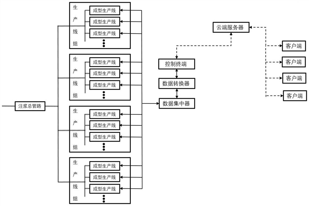
[0023] The invention provides a monitoring system for forming grouting pipelines, see figure 1 As shown, it includes multiple molding production lines and main grouting pipelines, and the molding production line is equipped with a control box.

[0024] The multiple molding production lines mentioned above are divided into multiple production line groups, the main grouting pipeline is connected to each production line group through a grouting sub-pipeline, and the grouting sub-pipelines pass through the molding production line in the production line group corresponding to the grouting branch pipeline connector . The monitoring system also includes:

[0025] The control terminal stores the shift schedules of multiple molding production lines. The shift schedule is based on the daily workload of the factory to plan the oper...


PUM


Abstract

The invention relates to a monitoring system and method for forming a grouting pipeline. The monitoring system comprises a plurality of forming production lines, a control terminal, a server and a client. The control terminal stores a scheduling schedule of the plurality of forming production lines, is electrically connected with the control box on each forming production line, sends the working state information of each forming production line to the server, and displays the working state information of each forming production line in a working interface form; the server is in communication connection with the control terminal, receives the working state information, sent by the control terminal, of each forming production line, and is further used for receiving a query request sent by the client and returning a query result to the client; and the client is in communication connection with the server. The method has the advantages that by increasing the number of the grouting circulation pipelines, the probability of grouting time coincidence is reduced, manual variation is reduced due to application of the monitoring system, and the scheme can effectively monitor the formed grouting time so as to reduce generation of forming bubbles.

Description

technical field [0001] The invention relates to the field of ceramic product production, in particular to a monitoring system and method for forming a grouting pipeline. Background technique [0002] Existing ceramic products are usually formed by grouting. The conventional production process is: the raw material department injects new slurry into the old tank for aging, and then injects the slurry in the old tank into the grouting tank for adjustment, so that the specific gravity, viscosity, and After the thickness and temperature reach the control range, the adjusted molding mud is pumped into the grouting pipeline by the injection pump, and then the mud is injected into the mold through the diaphragm pump. After the mud is formed in the plaster mold , the excess slurry in the mold is discharged into the slurry discharge barrel through the slurry pump. In order to improve production efficiency in the above process, multiple molding production lines are often set up in the...

Claims


Application Information

Patent Timeline
Patent Type & Authority Applications(China)
IPC IPC(8): B28B13/02B28B17/00
CPCB28B13/02B28B17/0063
Inventor 陆士峰倪永林曹建平
Owner LIXIL AS SANITARY MFG (SHANGHAI) CO LTD
Learn More