
Emergency power supply device with digital parameter display function

A technology of emergency power supply and digital display, which is applied in the direction of emergency power supply arrangements, circuit devices, electrical components, etc., can solve problems such as poor protection effects, and achieve the effects of protection, heat dissipation, and high temperature prevention

Pending Publication Date: 2022-03-18
DONGGUAN JUXING POWER
View PDF1 Cites 0 Cited by
  • Summary
  • Abstract
  • Description
  • Claims
  • Application Information

AI Technical Summary

Problems solved by technology

[0006] The purpose of the present invention is to provide an emergency power supply device with the function of digital display parameters to solve the defect of poor protection effect of the existing emergency power supply device

Method used


Image

  • Emergency power supply device with digital parameter display function
  • Emergency power supply device with digital parameter display function
  • Emergency power supply device with digital parameter display function

Examples


Embodiment 1

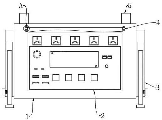
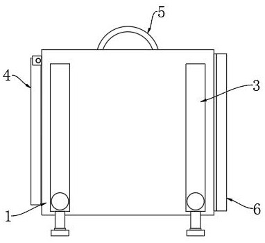
[0031] see Figure 1-6 , an embodiment provided by the present invention: an emergency power supply device with a digital display parameter function, including an emergency power supply main body 1, a plug-in board 2 and a handle 5, and one end of the emergency power supply main body 1 is provided with a plug-in board 2, and the plug-in The outer side of connecting plate 2 is provided with protective structure 4, and protective structure 4 comprises positioning table 401, rotating rod 402 and protective cover plate 403, and positioning table 401 is fixed on the top of one end of emergency power main body 1, and the inside of positioning table 401 is provided with rotating rod 402, one side of the rotating rod 402 is fixed with a protective cover 403, the cross section of the positioning platform 401 is greater than the cross section of the rotating rod 402, the positioning platform 401 and the rotating rod 402 constitute a rotatable structure, and both sides of the emergency po...

Embodiment 2

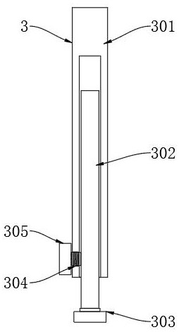
[0034] This embodiment also includes: the support structure 3 includes a positioning tube 301, an extension tube 302, a supporting foot 303, an adjustment hole 304 and an adjustment bolt 305, the positioning tube 301 is fixed on both sides of the main body of the emergency power supply 1, and the inside of the positioning tube 301 is provided with Extension pipe 302, the bottom end of extension pipe 302 is equipped with supporting foot 303, the bottom end of one side of positioning pipe 301 is provided with adjustment hole 304, the inside of adjustment hole 304 is provided with adjustment bolt 305, and positioning pipe 301 is on the emergency power supply main body 1 There are four groups fixed on the outside, the four groups of positioning tubes 301 are symmetrically distributed, the cross section of the positioning tube 301 is larger than that of the extension tube 302, the positioning tube 301 and the extension tube 302 form a telescopic structure, and the inside of the adjus...


PUM


Abstract

An emergency power supply device with a digital parameter display function disclosed by the present invention comprises an emergency power supply main body, a plug board and a handle, one end of the emergency power supply main body is provided with the plug board, the outer side of the plug board is provided with a protection structure, and the protection structure comprises a positioning table, a rotating rod and a protection cover plate. Supporting structures are arranged on the two sides of the emergency power supply body, a handle is installed at the top end of the emergency power supply body, and a heat dissipation structure is arranged at the other end of the emergency power supply body. The protection structure is arranged, the protection cover plate is arranged on the outer side of the plug board and covers the outer side of the supporting structure, the display screen and the plug port on the surface of the supporting structure can be protected, and the situation that when the display screen is not used, foreign objects enter the plug port in the supporting structure, and then the plug port and the device are damaged can be prevented; meanwhile, people can be prevented from touching the plugging port by mistake to cause dangers, and the protection performance of the emergency power supply device in use is realized.

Description

technical field [0001] The invention relates to the technical field of emergency power supply, in particular to an emergency power supply device with the function of digitally displaying parameters. Background technique [0002] In the outdoors or under special circumstances, it is generally not convenient to supply power to electronic equipment or small electrical equipment. At this time, the emergency power supply device is needed. The power requirements of the equipment; [0003] China Patent Authorization Announcement No. CN207504628U, announced on June 15, 2018, discloses an emergency power supply device, including a housing, a socket on the front of the housing, a USB interface and an indicator light on the left side of the housing, and a right side on the upper side of the housing. The remote control interface is set, the remote control interface is connected to the remote control through the control line, the remote control placement slot is set on the back of the s...

Claims


Application Information

Patent Timeline
Patent Type & Authority Applications(China)
IPC IPC(8): H02J9/00H05K7/20
CPCH02J9/00H05K7/2039
Inventor 廖跃飞
Owner DONGGUAN JUXING POWER
Learn More