Antenna and mobile terminal
A mobile terminal and antenna technology, applied in antennas, slot antennas, antenna coupling, etc., can solve the problems of terminal design, increase in manufacturing cost, crowded antenna wiring space, poor antenna radiation performance, etc., and achieve cost and space savings. Effect
- Summary
- Abstract
- Description
- Claims
- Application Information
AI Technical Summary
Problems solved by technology
Method used
Image
Examples
no. 1 example
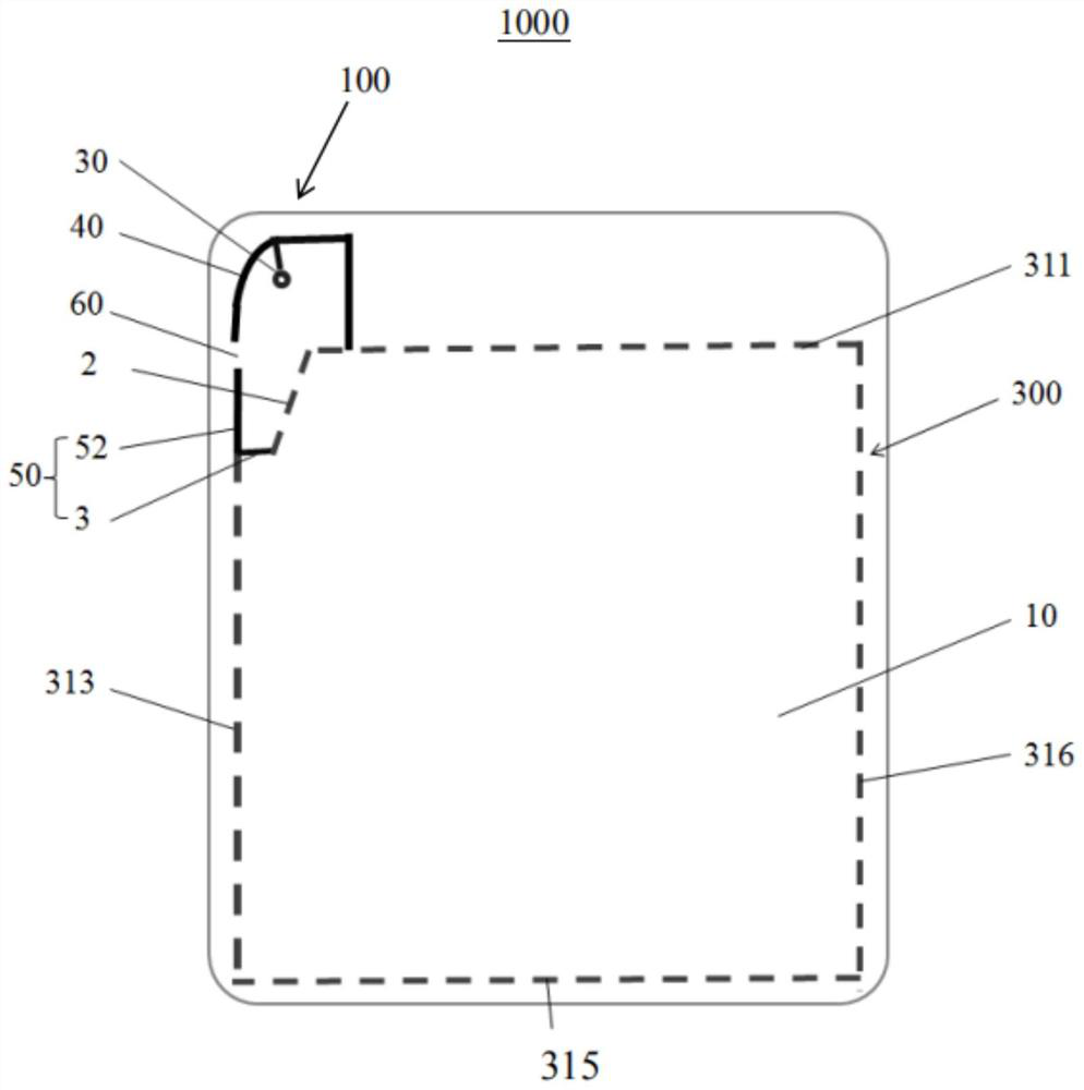
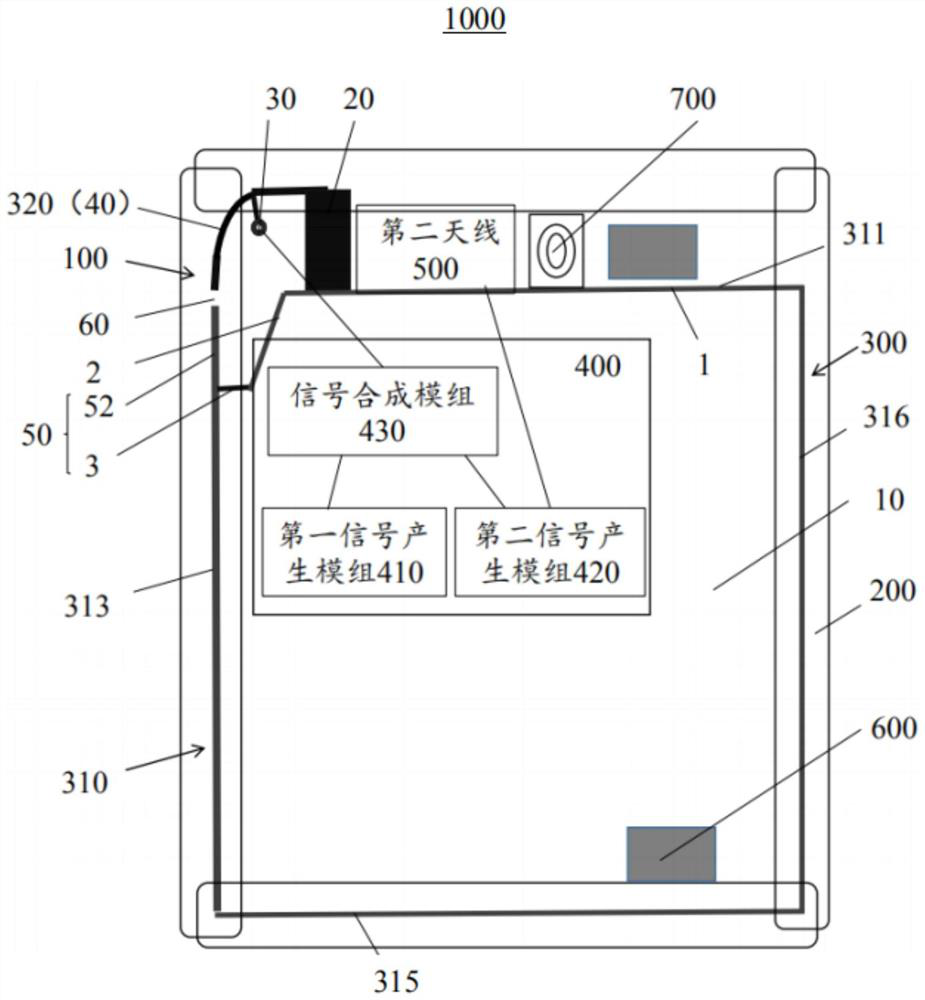
[0047] see figure 1 and figure 2 , figure 1 A schematic structural diagram of an antenna for implementing an embodiment of the present application, figure 2 It is a schematic structural diagram of a mobile terminal implementing an embodiment of the present application. In the embodiment of the present application, the mobile terminal 1000 includes an outer frame 200 and a middle case 300. The outer frame 200 can be made of plastic material. Optionally, the outer frame 200 can be formed by connecting four plastic parts end to end. , or the outer frame 200 can also be made by integral molding. Optionally, the middle case 300 may be made of metal material, which constitutes the metal frame of the mobile terminal 1000 . The middle case 300 includes a first functional frame 310 and a second functional frame 320, the number of the first functional frame 310 can be four, that is, the first functional frame 310 includes a first frame 311, a second frame 313 , the third frame 31...
no. 2 example
[0056] In order to facilitate understanding of the embodiments of the present application, the first antenna 100 on which the mobile terminal 1000 of the present application is based is described below.
[0057] In an antenna 100 provided in this application, the antenna 100 is used for the mobile terminal 1000, and the antenna 100 includes a feeding end 30, a first radiator 40, a second radiator 50 and a The gap 60 between the radiator 40 and the second radiator 50, the feeding end 30 is electrically connected to the first radiator 40, and provides a feeding signal for the first radiator 40, optionally , the first radiator 40 and the second radiator 50 are part of the metal frame of the mobile terminal.
[0058] Optionally, the antenna 100 may be a planar inverted F (Planar Inverted Antenna, PIFA) antenna.
[0059] In one embodiment, the first radiator 40 or the second radiator 50 generates an antenna signal according to the radiation of the feeding signal; and / or, the first...
no. 3 example
[0072] read on figure 2 , figure 2 It is a schematic structural diagram of a mobile terminal implementing an embodiment of the present application.
[0073] In the implementation manner of the present application, the mobile terminal 1000 further includes a signal generating unit 400 and a second antenna 500 .
[0074] Optionally, the antenna signals of the second antenna 500 may include MIMO Wi-Fi antenna signals, for example, MIMO 2.4G Wi-Fi signals and MIMO 5G Wi-Fi signals.
[0075] Optionally, the signal generating unit 400 is installed inside the mobile terminal 1000 and is close to the first frame 311 and the second frame 313 (ie, the second radiator 50 ). The second antenna 500 is disposed on the side of the first frame 311 away from the system ground 10 (that is, the second antenna 500 is located on the top of the mobile terminal 1000), and the second antenna 500 and the The second functional frame 320 (that is, the first radiator 40) is respectively located on o...
PUM
 Abstract
Description
Claims
Application Information
 - R&D
- Intellectual Property
- Life Sciences
- Materials
- Tech Scout
- Unparalleled Data Quality
- Higher Quality Content
- 60% Fewer Hallucinations
Browse by: Latest US Patents, China's latest patents, Technical Efficacy Thesaurus, Application Domain, Technology Topic, Popular Technical Reports.
© 2025 PatSnap. All rights reserved.Legal|Privacy policy|Modern Slavery Act Transparency Statement|Sitemap|About US| Contact US: help@patsnap.com


