
Flow guide device of artificial regulation and storage lake in sponge city

A sponge city, artificial technology, applied in water supply installations, water conservancy projects, river regulation and other directions, can solve the problems of water circulation in the lake body, it is difficult to realize, and the area of ​​the lake cannot be used together, so as to promote water circulation. , save cost, improve water quality and landscape effect

Pending Publication Date: 2022-03-18
MCC TIANGONG GROUP
View PDF0 Cites 0 Cited by
  • Summary
  • Abstract
  • Description
  • Claims
  • Application Information

AI Technical Summary

Problems solved by technology

At present, the purpose of the artificial storage lake is to optimize the water flow conditions to avoid "short flow" and to fully purify the water body through the lake body. The rainwater inlet and outlet are mostly arranged along the diagonal direction of the lake body. This arrangement is easy to realize in the new drainage planning area. , but in the spongy transformation of the old city with a relatively high degree of construction, when adding a storage lake to the original pipeline, the positions of the water inlet and outlet on both sides have been fixed, and this arrangement is difficult to achieve
[0003] The existing pipes are transformed into sponges, and the positions of the water inlet and outlet pipes on both sides are fixed. Direct use will cause the newly incoming rainwater to follow the "short flow effect" and be discharged directly according to the shortest path without flowing through the entire lake body, making it impossible for the entire lake body to circulate water. , become "dead water", forcing relevant purification measures, the aquatic animal and plant communities can only be arranged on the side of the water inlet and outlet pipes, and the lake area cannot be used together

Method used


Image

  • Flow guide device of artificial regulation and storage lake in sponge city
  • Flow guide device of artificial regulation and storage lake in sponge city
  • Flow guide device of artificial regulation and storage lake in sponge city

Examples


Embodiment 1

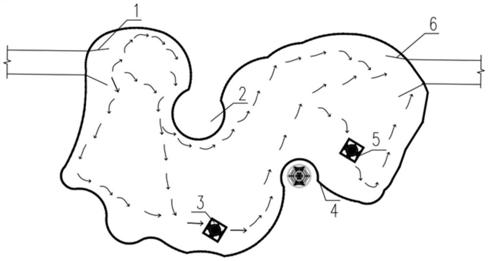
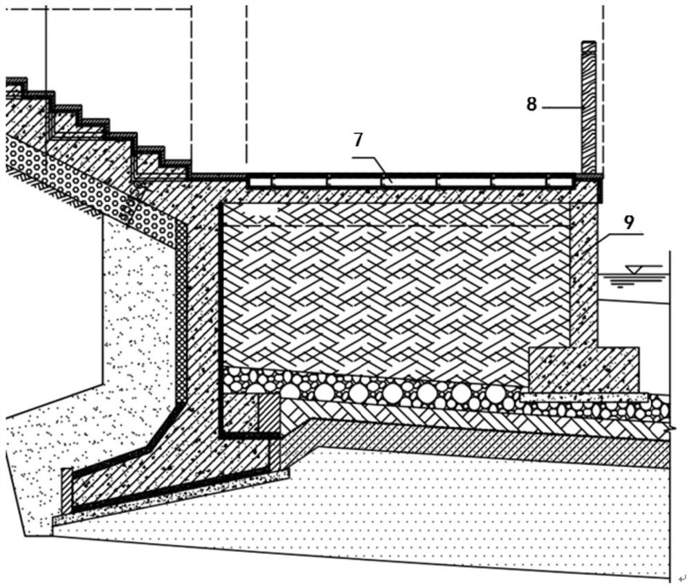
[0031] The water inlet area 1 and the water outlet area 6 are designed and installed in the artificial storage lake, and the water inlet area 1 and the water outlet area 6 are respectively located at the two ends of the artificial storage lake, and the first diversion dam is designed and built in the lake 2 and the second diversion dam 4, the two diversion dams make the artificial storage lake s-shaped, forming a shape similar to a river to promote water flow; the first diversion dam 2 and the second diversion dam 4 include a retaining wall 9, The height of the retaining wall 9 is at least 50cm higher than the normal water level of the artificial storage lake; A water pump pusher 3 is installed in the lake, and a submersible pump 5 is installed in the artificial storage lake near the second diversion dam 4 .

[0032] After the artificial storage lake is filled with lake water, more new rainwater will flow into the lake in rainy days. The artificial storage lake needs to divert...


PUM


Abstract

The invention belongs to the technical field of rainwater regulation and storage of sponge cities, and particularly relates to a diversion system of a manual regulation and storage lake of a sponge city, which comprises a water inlet area, a water outlet area, a diversion dam, a water pump water impeller and a submersible pump, and is characterized in that the water inlet area and the water outlet area are respectively arranged at two ends of the manual regulation and storage lake; the water pump water impeller and the submersible pump are respectively installed in the lake and cooperate with each other to further promote water body circulation and adjust the water body flow direction again. The method has the beneficial effects that the water quality and the landscape effect are improved, an original drainage pipeline can be normally used, new rainwater pipelines are avoided, the manufacturing cost is saved, and the method has wide application prospects in spongy transformation in old cities.

Description

technical field [0001] The invention belongs to the technical field of rainwater regulation and storage in sponge cities, and in particular relates to a diversion system for artificial regulation and storage lakes in sponge cities. Background technique [0002] The storage lake is an important way to store, purify and reuse rainwater in the concept of sponge city. In addition to using natural lakes, cities often use artificial lakes for rainwater storage. Artificial lakes are placed between rainwater drainage pipes. According to the sponge city regulation and storage index, the rainwater that needs to be stored is stored in the lake to ease drainage. The pressure will be discharged after the peak rainfall period is over. At present, the purpose of the artificial storage lake is to optimize the water flow conditions to avoid "short flow" and to fully purify the water body through the lake body. The rainwater inlet and outlet are mostly arranged along the diagonal direction o...

Claims


Application Information

Patent Timeline
IPC IPC(8): E02B1/00E02B3/02E03F5/10
CPCE02B1/00E02B3/02E03F5/103E03F5/107
Inventor 张鹏飞
Owner MCC TIANGONG GROUP
Learn More