Cloth clamping tabouret

An embroidery frame and cloth clamping technology, which is applied in the field of embroidery machines, achieves the effects of good structural stability, labor-saving disassembly and assembly, and simple structure

Pending Publication Date: 2022-03-18
ZHUJI CHUANGJIA ELECTRONICS EQUIP
View PDF13 Cites 1 Cited by
  • Summary
  • Abstract
  • Description
  • Claims
  • Application Information

AI Technical Summary

Problems solved by technology

[0010] The technical problem to be solved by the present invention is to provide a structure-improved clamping embroidery frame to solve the technical defects of the cloth clamping embroidery frame and the automatic clamping embroidery frame in the prior art

Method used


Image

  • Cloth clamping tabouret
  • Cloth clamping tabouret
  • Cloth clamping tabouret

Examples


Embodiment 1

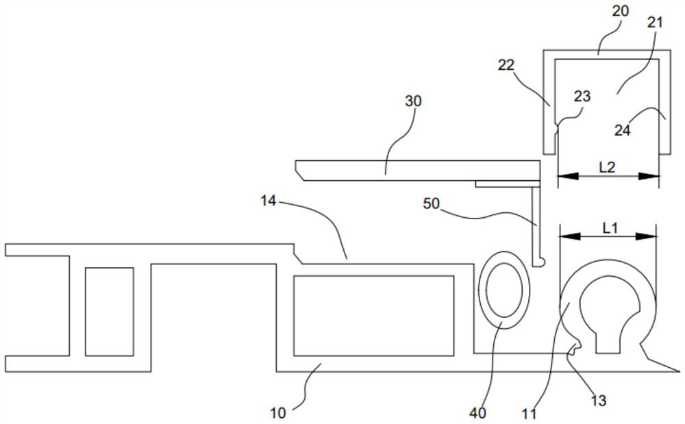
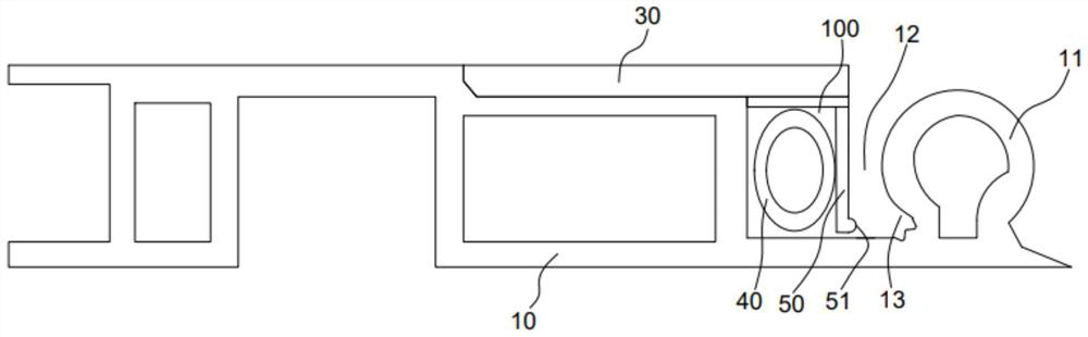
[0043] A cloth embroidery frame of this embodiment consists of Figure 1-3 The frame unit 10 shown constitutes. In this embodiment, one side of the frame unit 10 is provided with a fabric support unit 11, and the fabric support unit 11 is located inside the cloth clamping embroidery frame.

[0044] In this embodiment, the frame unit 10 is provided with a driving chamber 100 , the side of the driving chamber 100 facing the fabric supporting unit 11 is a movable wall 50 , and an active zone 12 is formed between the movable wall 50 and the fabric supporting unit 11 .

[0045] As a preference, in this embodiment, the top of the frame unit 10 is provided with an installation groove 14, and the cover plate 30 is fixedly installed in the installation groove 14, and the movable wall 50 is installed on the lower end of the cover plate 30 facing the fabric support unit 11. Part of the plate 30 forms the top wall of the drive chamber.

[0046] In this embodiment, the movable mode of th...

Embodiment 2

[0055] The cloth embroidery frame of this embodiment differs from Embodiment 1 in that, as Image 6 As shown, the drive system includes an eccentric rod 43 disposed in the drive cavity and a rotary drive mechanism (not shown in the figure, usually a motor) for driving the eccentric rod 43 to rotate. In this embodiment, the movement of the movable wall relative to the direction of the cloth supporting unit is realized through the rotational movement of the eccentric rod 43 .

Embodiment 3

[0057] The cloth embroidery frame of this embodiment differs from Embodiment 1 in that, as Figure 7 As shown, the lower end of the movable wall 50 is connected to the bottom of the drive chamber, and the upper end of the movable wall is a free-moving end.

[0058] Among them, in this embodiment, similar to Embodiment 1, the movable mode of the movable wall 50 is a feasible implementation mode that its lower end is hinged with the frame unit; another feasible mode is that the lower end of the movable wall 50 is hinged with the frame unit The units are fixedly connected, but the movable wall itself is made of elastic material with a certain degree of elasticity, such as spring steel, which can be reset after deformation.

[0059] It should be noted that, the driving system of this embodiment can be either the driving system of the first embodiment or the driving system of the second embodiment.


PUM


Abstract

The invention relates to the technical field of embroidery machines, and particularly discloses a cloth clamping tabouret which at least comprises a frame unit, a cloth supporting unit, a movable wall, a driving system and a cloth pressing structure, the cloth pressing structure is provided with a containing cavity, the two sides of the containing cavity are a first cavity wall and a second cavity wall respectively, the minimum distance between the first cavity wall and the second cavity wall is L2, and L2 is larger than L2. The maximum width of the cloth supporting unit is L1, L1 is smaller than or equal to L2, and the thickness of the first cavity wall is smaller than the width of the movable interval. According to the structure, no resistance exists between the cloth pressing structure and the cloth supporting unit in the process of disassembling and assembling the cloth pressing structure from the cloth supporting unit, compared with a cloth clamping structure, disassembly and assembly are labor-saving, fabric cannot be damaged in the disassembly and assembly process, and the clamping device can adapt to clamping of fabric of different specifications; the driving system is arranged on the frame unit, the position of the driving system is fixed, a related pipeline structure cannot move in the fabric disassembling and assembling process, the structure is simpler, the cost is lower, the structural layout is more reasonable and reliable, and the structural stability is better.

Description

technical field [0001] The invention relates to the technical field of embroidery machines, in particular to a cloth-clip embroidery frame. Background technique [0002] The embroidery frame of the traditional embroidery machine, as the composite material embroidery frame of the computerized embroidery machine disclosed by the Chinese utility model patent CN2293578Y as the notification number, with reference to the appendix of this patent figure 2 And attached image 3 , wherein the cloth is fixed by the cloth holding post 3 and the cloth clamp 5. The technical defects of this type of cloth fixing method are as follows: [0003] (1) The clamping force of the fabric clamp 5 cannot be adjusted, if the clamping force is too large, it is easy to leave indentations on the fabric and even damage the fabric; if the clamping force is too small, the fabric cannot be effectively fixed; [0004] (2) The thickness of the fabrics commonly used for embroidery is different. Since the cl...

Claims


Application Information

Patent Timeline
IPC IPC(8): D05C9/04
CPCD05C9/04
Inventor 陈伟星陈韦东
Owner ZHUJI CHUANGJIA ELECTRONICS EQUIP
Why Eureka
Try Eureka