
Assembling mold

A technology of molds and guide rods, which is applied in the direction of manufacturing tools, workpiece clamping devices, climate sustainability, etc., and can solve problems such as difficulty in ensuring parallelism of input axes

Active Publication Date: 2022-03-18
YANGZHOU HENGDE IND TECH CO LTD
View PDF9 Cites 0 Cited by
  • Summary
  • Abstract
  • Description
  • Claims
  • Application Information

AI Technical Summary

Problems solved by technology

[0005] This application provides an assembly mold, which is used to solve the problem in the prior art that it is difficult to ensure that the shaft flat position of the input shaft is parallel to the shaft flat position of the output shaft when the input shaft and the output shaft are assembled and docked through a coupling

Method used


Image

  • Assembling mold
  • Assembling mold
  • Assembling mold

Examples


Embodiment Construction

[0044] The implementation manner of the present application will be further described in detail below with reference to the drawings and embodiments. The following examples are used to illustrate the present application, but cannot be used to limit the scope of the present application.

[0045] In the description of the embodiments of the present application, it should be noted that the terms "center", "vertical", "transverse", "upper", "lower", "front", "rear", "left", "right" , "vertical", "horizontal", "top", "bottom", "inner", "outer" and other indicated orientations or positional relationships are based on the orientations or positional relationships shown in the drawings, and are only for the convenience of describing this The application embodiments and simplified descriptions do not indicate or imply that the devices or elements referred to must have a specific orientation, be constructed and operated in a specific orientation, and therefore should not be construed as ...


PUM


Abstract

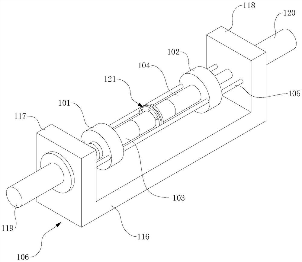
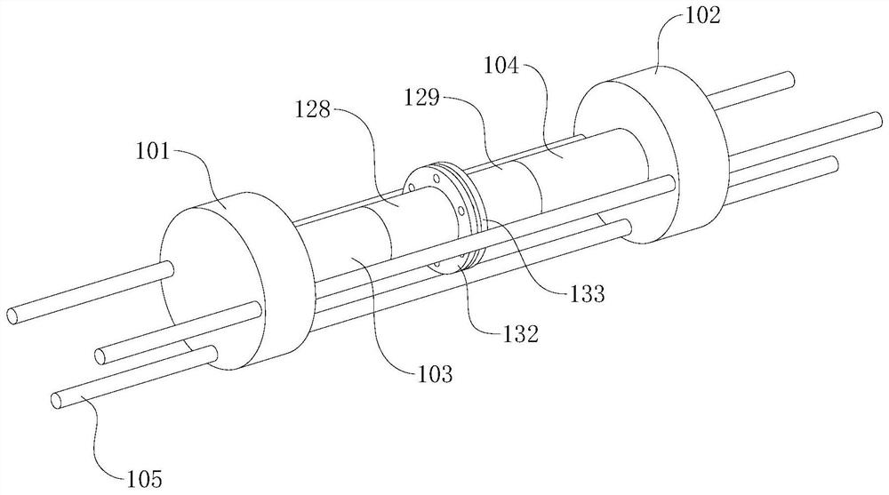
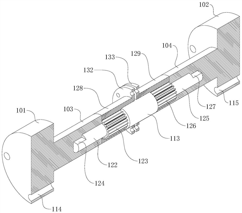
The invention provides an assembling mold which comprises a first sliding block, a second sliding block, a first ejector block, a second ejector block, a guide rod and a base, the guide rod is fixedly connected with the base, the first sliding block is in sliding connection with the guide rod, and the second sliding block is in sliding connection with the guide rod; a first positioning groove is formed in the end, close to the second ejector block, of the first ejector block, a second positioning groove is formed in the end, close to the first ejector block, of the second ejector block, the central axis of the first positioning groove and the central axis of the second positioning groove are located on the same straight line, a first hole flat position is arranged on the inner wall of the first positioning groove, and a second hole flat position is arranged on the inner wall of the second positioning groove. And the first hole flat position is parallel to the second hole flat position. The first hole flat position and the second hole flat position are in a mutually parallel state, in the splicing process, the first shaft flat position is matched with the first hole flat position, the second shaft flat position is matched with the second hole flat position, and it can be ensured that the first shaft flat position and the second shaft flat position are kept in a parallel state after splicing is completed.

Description

technical field [0001] The present application relates to the technical field of molds, in particular to an assembled mold. Background technique [0002] There is a type of assembly mold in the prior art, which is used to assemble precision parts. For example, when assembling two drive shafts (input shaft and output shaft) in the prior art, a coupling is usually used for assembly and docking Generally, splines are arranged on the outer walls of the ends of the input shaft and output shaft. The thickness of the teeth of the splines is small, and blades parallel to the axial direction are formed on the sides of the input shaft and output shaft. The two ends of the coupling The diameter of the inner wall is slightly smaller than the diameter of the end of the input shaft and output shaft When inserting the end of the input shaft and output shaft into the end of the coupling, the spline will cut the inner wall of the port of the coupling along the axial direction, and after the ...

Claims


Application Information

Patent Timeline
IPC IPC(8): B25B11/02
CPCB25B11/02Y02P70/50
Inventor 宰广平
Owner YANGZHOU HENGDE IND TECH CO LTD
Learn More