Infrared light liquid drop detection device and method

A detection device and infrared light technology, which is applied in flow monitors, flow control, non-electric variable control, etc., can solve the problems of reducing droplet detection accuracy, reducing droplet detection accuracy, and inaccurate infusion volume, etc., to improve The effect of detection accuracy, prevention of missed detection, and accurate infusion volume

Active Publication Date: 2022-03-18
广东德澳智慧医疗科技有限公司
View PDF10 Cites 0 Cited by
  • Summary
  • Abstract
  • Description
  • Claims
  • Application Information

AI Technical Summary

Problems solved by technology

However, although this gravity infusion device droplet detection device can detect the droplet and count the number of dropped drops, in the actual use process, the following technical defects are still found: 1. Shaking, the dropper drives the drip nozzle to shake synchronously, causing the undripped liquid droplets hanging at the end of the drip nozzle to shake, and the shaking liquid droplets reciprocally block the infrared beam, resulting in the continuous generation of photoelectric fluctuation signals at the infrared receiving end, which in turn leads to The infrared receiving end misjudged that there was a droplet dripping, which eventually led to inaccurate infusion volume, which greatly reduced the detection accuracy of the droplet
2. Under external factors, the dropper is tilted, and the dropper drives the drip nozzle to tilt synchronously. When the drip nozzle and the direction of gravity form the largest inclination angle, the dripping drops do not drip downward along the vertical direction, but It is to bypass the infrared beam dripping, causing the infrared receiving end to not detect the droplet, resulting in the phenomenon of missed detection, and finally resulting in the inaccurate infusion volume, which greatly reduces the detection accuracy of the droplet

Method used


Image

  • Infrared light liquid drop detection device and method
  • Infrared light liquid drop detection device and method
  • Infrared light liquid drop detection device and method

Examples


Embodiment Construction

[0056] The present invention will be further described below in conjunction with accompanying drawing, protection scope of the present invention is not limited to the following:

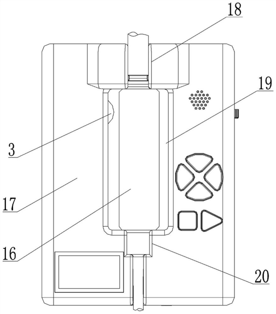
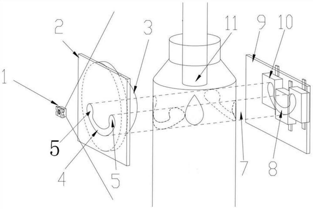
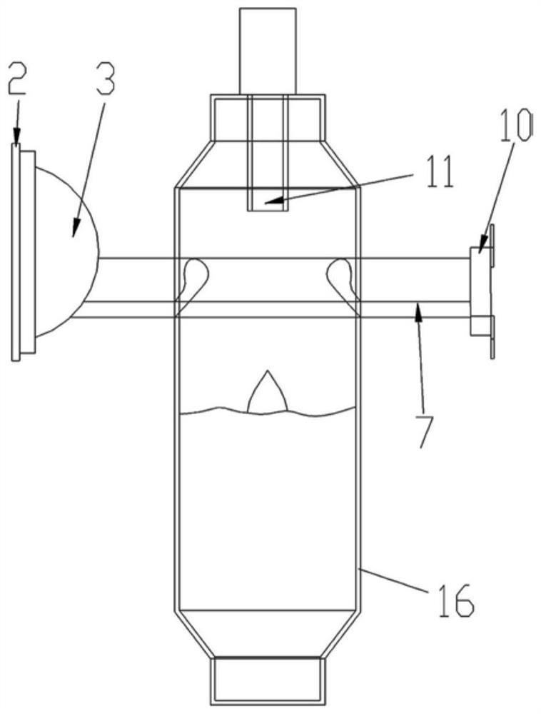
[0057] Such as Figure 1~2 Shown, a kind of infrared light liquid drop detection device, it comprises dropper 16, drop nozzle 11 and casing 17, and the end port of described drop nozzle 11 is communicated with dropper 16, and dropper 16 is Mo Fei's dropper, The front end surface of the casing 17 is successively provided with an upper U-shaped slot 18, a through slot 19 and a lower U-shaped slot 20 from top to bottom, and the through slot 19 runs through the front and rear end faces of the casing 17. In the through groove 19, and the upper and lower ends of the dropper 16 are respectively fixed in the upper U-shaped slot 18 and the lower U-shaped slot 20. The receiving device, the infrared emitting device and the infrared receiving device are respectively arranged on the left and right sides of the d...


PUM

PropertyMeasurementUnit
beam angleaaaaaaaaaa

Abstract

The invention discloses an infrared light liquid drop detection device and method.The infrared transmitting device comprises an infrared transmitting tube (1), a light shading piece (2) and a lens (3) which are sequentially arranged from left to right, the convex face of the lens (3) extends into a through groove (19) and is located below a dripping nozzle (11), and an arc-shaped gap (4) used for light passing is formed in the end face of the light shading piece (2); the arc-shaped gap (4) is overlapped with the lower half part of the plane of the lens (3), the length of the arc-shaped gap (4) is smaller than the diameter of the convex surface of the lens (3), and the convex surfaces of the infrared transmitting tube (1) and the lens (3) are located on the same water surface line; the infrared receiving device comprises an infrared light-transmitting piece (9) fixedly arranged in the machine shell (17), and an infrared receiving array (10) is fixedly arranged on the left end face of the infrared light-transmitting piece (9). The liquid drop detection device has the beneficial effects that the structure is compact, the detection reliability is high, false detection and missing detection are avoided, and the liquid drop detection precision is improved.

Description

technical field [0001] The invention relates to the technical field of liquid drop detection, in particular to an infrared light liquid drop detection device and method. Background technique [0002] The gravity infusion set is used to deliver medicine to the patient. The gravity infusion set includes a dropper and a drip nozzle. The dropper is set on the top of the dropper, and its end port extends into the dropper. After the infusion tube is connected, the medicine liquid flowing out of the infusion bottle or infusion bag through the infusion tube enters the drip nozzle, and gradually gathers into droplets at the end of the drip nozzle. After gathering to a certain size, the droplets fall and drop into the dropper. Finally, the medicinal liquid in the dropper is delivered to the patient. In order to facilitate doctors to know the completed dose of medicine in real time during the infusion to understand the progress of the infusion, it is currently necessary to use a gravi...

Claims


Application Information

Patent Timeline
Patent Type & Authority Applications(China)
IPC IPC(8): A61M5/168
CPCA61M5/1689A61M2205/3334
Inventor 王洪平
Owner 广东德澳智慧医疗科技有限公司
Why Eureka
Try Eureka