
Control circuit of power converter

A technology of power converters and control circuits, which is applied in the direction of output power conversion devices, electrical components, DC power input conversion to DC power output, etc. It can solve problems affecting system stability and instability of inductor current IL in power conversion circuits. , to achieve the effect of maintaining stable output current and improving stability

Pending Publication Date: 2022-03-15
UPI SEMICON CORP
View PDF0 Cites 0 Cited by
  • Summary
  • Abstract
  • Description
  • Claims
  • Application Information

AI Technical Summary

Problems solved by technology

When using a capacitive element with a small parasitic resistance (such as a ceramic capacitor) as the output capacitor, since the feedback control of the power conversion circuit is only affected by the output capacitor, the difference between the output voltage ripple (Ripple) and the PWM signal There is a phase difference (Phase difference), thus affecting the stability of the system
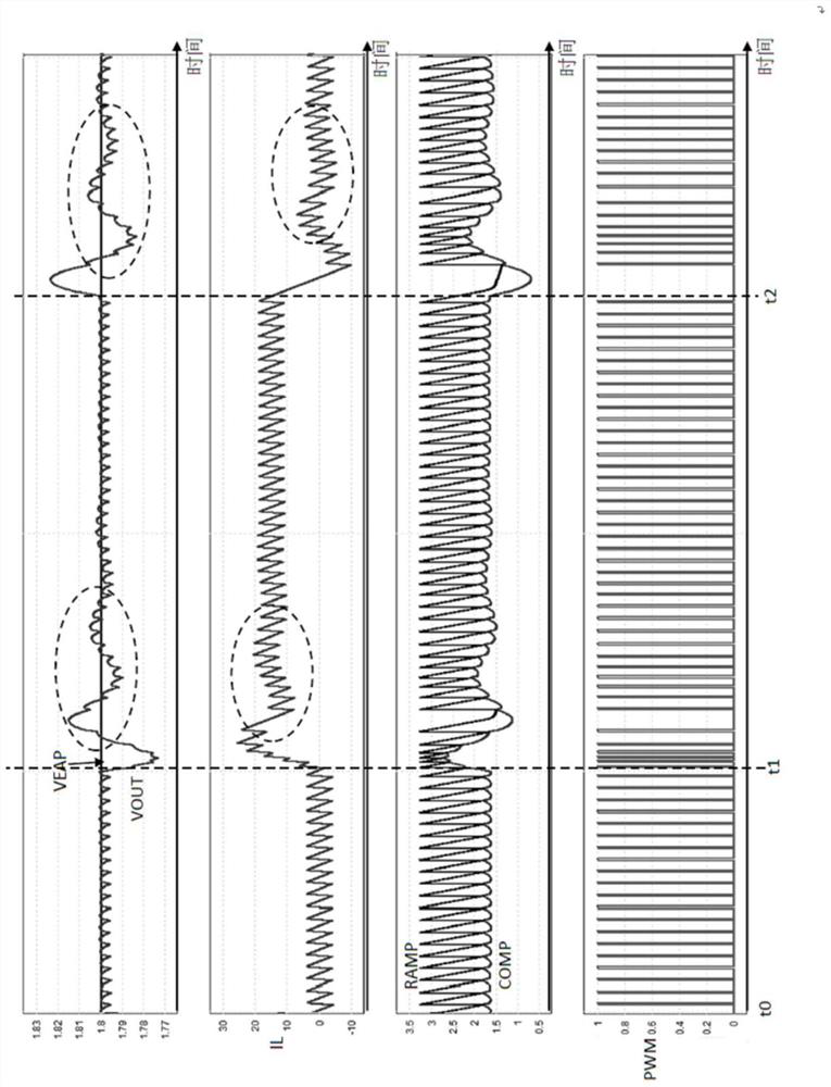
[0003] For example, if figure 1 As shown, when the resistance value of the equivalent series resistance of the output capacitor (hereinafter referred to as the output resistance) is small, the output voltage VOUT of the power conversion circuit will oscillate up and down for many times after pumping / unloading and deviate from the ringing of the reference voltage VEAP (Ringing ) phenomenon, which will cause the inductance current IL of the power conversion circuit to become unstable, seriously affecting the stability of the system

Method used


Image

  • Control circuit of power converter
  • Control circuit of power converter
  • Control circuit of power converter

Examples


Embodiment Construction

[0064] Reference will now be made in detail to the exemplary embodiments of the present invention, examples of which are illustrated in the accompanying drawings. Elements / members with the same or similar numbers used in the drawings and embodiments are used to represent the same or similar parts.

[0065] A specific embodiment according to the present invention is a control circuit of a power converter. In this embodiment, the control circuit can be applied to a single-phase or multi-phase power converter, depending on actual needs.

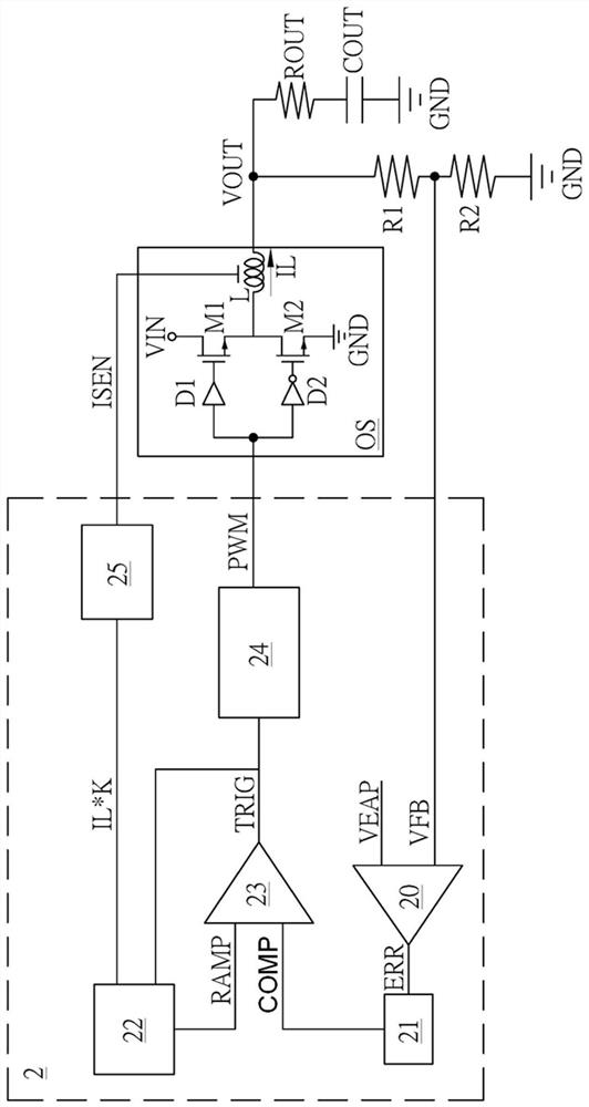
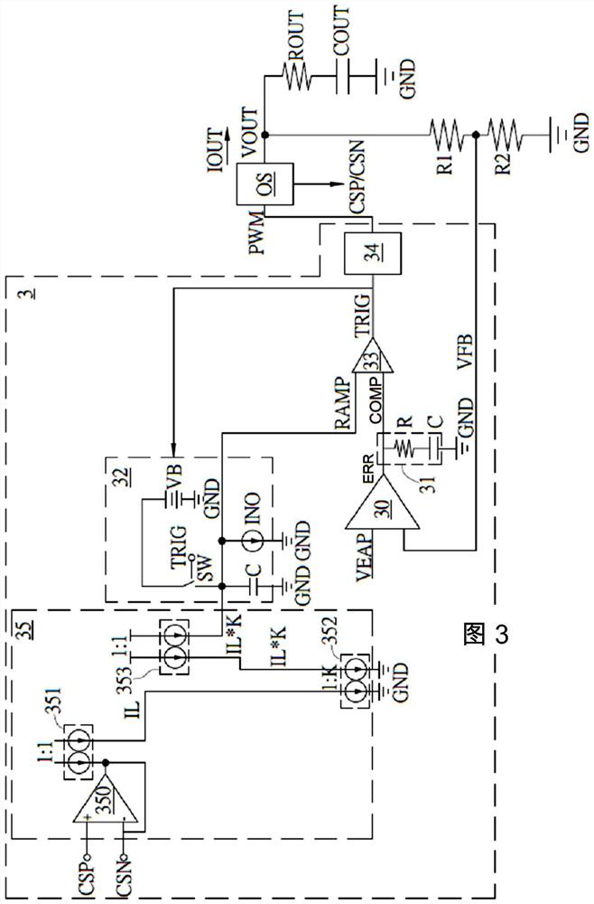
[0066] Please refer to figure 2 . figure 2 A schematic diagram of the control circuit of the power converter in this embodiment. Such as figure 2 As shown, the control circuit 2 is applied to a single-phase power converter with a single output circuit OS. The control circuit 2 is coupled to the output circuit OS. The voltage dividing resistors R1 and R2 are connected in series between the output circuit OS and the ground terminal GND. ...


PUM


Abstract

A control circuit of a power converter comprises a sensing circuit, a ramp signal generator, an error amplifier, a comparator and a pulse width modulation circuit. The sensing circuit is coupled to the first output circuit to provide a current sensing signal. The ramp signal generator is coupled to the sensing circuit and receives the current sensing signal to provide a ramp signal. The error amplifier receives a reference voltage and an output feedback voltage of the power converter to provide an error amplification signal. The comparator is coupled to the ramp signal generator and the error amplifier and receives the ramp signal and the error amplification signal to provide a control signal. The pulse width modulation circuit is coupled between the comparator and the first output circuit, receives the control signal and provides a pulse width modulation signal to control the first output circuit. The ramp signal generator adjusts a slope of the ramp signal according to the current sensing signal. According to the invention, the ringing phenomenon of the output voltage of the power converter after pumping / unloading can be avoided, so that the stability of system output is improved.

Description

technical field [0001] The invention relates to a power converter, in particular to a control circuit of the power converter. Background technique [0002] In a traditional power conversion circuit, the output capacitor is connected in series between the output terminal and the ground terminal, and the power conversion circuit uses the capacitance value of the output capacitor and its equivalent series resistor (ESR) for feedback control. When using a capacitive element with a small parasitic resistance (such as a ceramic capacitor) as the output capacitor, since the feedback control of the power conversion circuit is only affected by the output capacitor, the difference between the output voltage ripple (Ripple) and the PWM signal There is a phase difference between them, which affects the stability of the system. [0003] For example, if figure 1 As shown, when the resistance value of the equivalent series resistance of the output capacitor (hereinafter referred to as th...

Claims


Application Information

Patent Timeline
Patent Type & Authority Applications(China)
IPC IPC(8): H02M1/088H02M1/32
CPCH02M1/088H02M1/32H02M1/0009H02M3/158H02M1/0025
Inventor 洪伟修
Owner UPI SEMICON CORP
Learn More