
Pipe jacking device, construction device and construction method of subsurface tunnel

A technology for construction devices and jacking devices, which can be used in tunnels, earthwork drilling, mining equipment, etc., and can solve problems such as lack of stable excavation face

Pending Publication Date: 2022-03-15
CHINA RAILWAY ENGINEERING EQUIPMENT GROUP CO LTD
View PDF1 Cites 0 Cited by
  • Summary
  • Abstract
  • Description
  • Claims
  • Application Information

AI Technical Summary

Problems solved by technology

[0004] The purpose of the present invention is to provide a pipe jacking device for underground excavation tunnels to solve the problem that the pipe jacking construction devices in the prior art do not have the function of stabilizing the excavation tunnel face in unstable strata or strata requiring high settlement. Technical problem; Correspondingly, the object of the present invention is also to provide a kind of construction device of underground excavation tunnel, to solve the problem that the tunnel construction device in the prior art does not have the stable excavation handle in the unstable stratum or the stratum with higher settlement requirements. The technical problem of subsurface function; Correspondingly, the object of the present invention is also to provide a kind of construction method of underground excavation tunnel, to solve the tunnel construction method in the prior art and apply in the stratum with higher requirement of settlement or settlement The technical problem of not having the function of stably excavating the tunnel face

Method used


Image

  • Pipe jacking device, construction device and construction method of subsurface tunnel
  • Pipe jacking device, construction device and construction method of subsurface tunnel
  • Pipe jacking device, construction device and construction method of subsurface tunnel

Examples


Embodiment 1

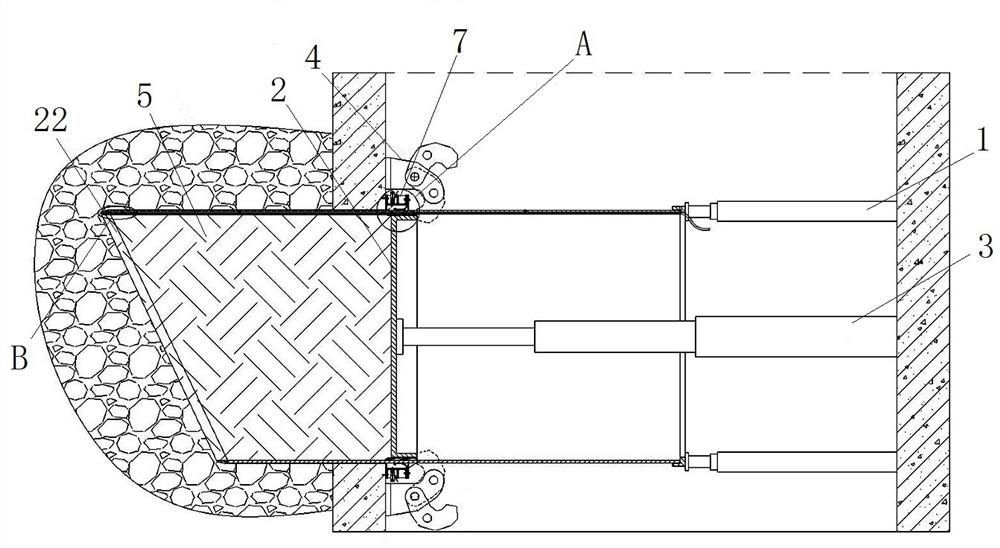
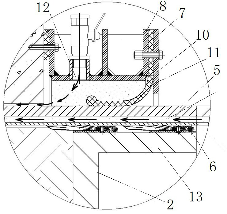
[0099] Such as figure 1 As shown, the construction device for underground excavation tunnel includes a pipe jacking device and a working pipe 5 arranged in the originating shaft. The working pipe 5 is located at the front end of the pipe jacking device. The pipe jacking device includes a pipe jacking device 1, 1 is a pipe jacking telescopic cylinder. In this embodiment, the pipe jacking telescopic cylinder is a pipe jacking hydraulic cylinder. The pipe jacking hydraulic cylinder can expand and contract in the front and rear directions. The end face is used to push and cooperate with the working pipe 5 to drive the working pipe 5 to push forward into the soil layer.

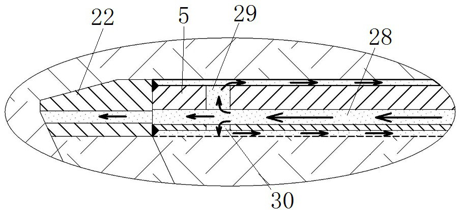
[0100] In this example, if figure 1 and image 3 As shown, there are multiple working tubes 5. During the tunnel excavation process, multiple working tubes 5 are pushed into the soil layer one by one, and are located at the angle between the front end face of the front end working tube 5 and the central axis of ...

specific Embodiment 2

[0115] The difference with specific embodiment 1 is:

[0116] Such as Figure 7 to Figure 9 As shown, in the construction device of the underground excavation tunnel, the front end of the front end working tube 5 is equipped with cutting teeth 23, and the cutting teeth 23 are evenly arranged in the circumferential direction of the front end working tube 5 in a fork structure, so as to improve the penetration of the working tube 5 into the soil layer. speed.

[0117] In the pipe jacking device of underground excavation tunnel, such as Figure 7 and Figure 8 As shown, it also includes a circumferential turning device 16, which is installed between the pipe jacking hydraulic cylinder and the working pipe 5, and the circumferential turning device 16 is used to push the working pipe 5 in the pipe jacking hydraulic cylinder. During the process, the working pipe 5 is pushed into the soil layer in a reciprocating manner in the circumferential direction.

[0118] Specifically, such ...

specific Embodiment 3

[0126] The difference from the specific embodiment 1 is that the circumferential rotation structure includes a rotary drive mechanism, and the rotary drive mechanism includes a motor and a meshing gear. The motors are arranged in pairs, and the paired two motors are respectively fixed on the radial sides of the working tube. The motors Fixed on the fixed top iron, the output shaft of the motor is provided with an output gear, and the outer peripheral surface of the hoop is provided with a rack meshed with the output gear. When the working pipe is pushed into the soil layer, the two motors act synchronously. The positive and negative rotation of the motor drives the working tube to perform reciprocating rotary motion in the circumferential direction. The difference from the construction process of the construction device for the underground excavation tunnel in the specific embodiment 1 is that in step (2), during the process of the working pipe moving forward relative to the se...


PUM


Abstract

The invention relates to a pipe jacking device, a construction device and a construction method of a subsurface tunnel. The construction device of the subsurface tunnel comprises a pipe jacking device and a working pipe, the pipe jacking device comprises a pipe jacking pushing device, a sealing plate, a sealing plate pushing device and a sealing plate limiting device, and the sealing plate keeps a sealing state for a soil body in the working pipe under the pushing action of the sealing plate pushing device; the sealing plate limiting device limits the position of the sealing plate when the jacking pipe pushing device and the sealing plate pushing device retract backwards, so that the position of the sealing plate is not changed; according to the construction method, in the process of jacking the working pipe into the soil layer and the process of connecting the next section of working pipe, the sealing plate is kept in a sealing state until the working pipe penetrates through the soil layer, the sealing plate is dismantled, and a soil body is excavated. By means of the construction device and the construction method, soil in the working pipe can be effectively prevented from gushing out of the tunnel portal, the function of stabilizing the tunnel face is achieved, and the adaptability of the construction device and the construction method to unstable stratums or stratums with the high settlement requirement can be improved.

Description

technical field [0001] The invention relates to the technical field of pipe jacking construction, in particular to a pipe jacking device, a construction device and a construction method for an underground excavation tunnel. Background technique [0002] Full-section tunnel boring machines such as shield machines and pipe jacking machines have the advantages of fast construction speed, high safety, good forming quality, and underground excavation construction. They have been widely used in construction fields such as municipal pipelines and traffic tunnels. However, shield machines, The structure of the pipe jacking machine is complicated, and the cost of equipment and construction is high. [0003] In addition to the above-mentioned full-section tunneling machinery, some projects also use the open tool tube construction method. The invention patent document with the authorized announcement number CN106402490B discloses a method of pipe jacking in silt soil layer based on ste...

Claims


Application Information

Patent Timeline
IPC IPC(8): E21D9/11
CPCE21D9/11
Inventor 贾连辉薛广记范磊贺开伟李治龚廷民
Owner CHINA RAILWAY ENGINEERING EQUIPMENT GROUP CO LTD
Learn More