Guide mechanism for CT puncture intervention

A technology of guiding mechanism and puncture needle, which is applied in the direction of puncture needle, application, inoculation and ovulation diagnosis, etc. It can solve the problems of adjusting biopsy needle, secondary injury, needle offset, etc., to prevent lateral vibration, avoid secondary injury, prevent The effect of too fast

Inactive Publication Date: 2022-03-15
HENAN UNIV HUAIHE HOSPITAL
View PDF0 Cites 0 Cited by
  • Summary
  • Abstract
  • Description
  • Claims
  • Application Information

AI Technical Summary

Problems solved by technology

[0003] Before the puncture, the biopsy needle needs to be adjusted to an appropriate angle. At present, a guide mechanism is usually used to guide the biopsy needle to assist the biopsy needle to penetrate into an accurate position and avoid secondary injury to the patient. However, the existing guidance The biopsy needle puncture device cannot adjust the puncture angle of the biopsy needle at multiple angles, which is not very practical, and the biopsy needle may vibrate during the actual operation of the biopsy needle by medical personnel, which will cause the needle to deviate, which is not conducive to Accurately sample tissue at the target location
[0004] Therefore, it is necessary to design a biopsy needle that can adjust the angle of the biopsy needle in multiple directions to control the puncture direction, Guidance mechanism for CT puncture intervention that can sufficiently and effectively prevent needle deviation

Method used


Image

  • Guide mechanism for CT puncture intervention
  • Guide mechanism for CT puncture intervention
  • Guide mechanism for CT puncture intervention

Examples


Embodiment 1

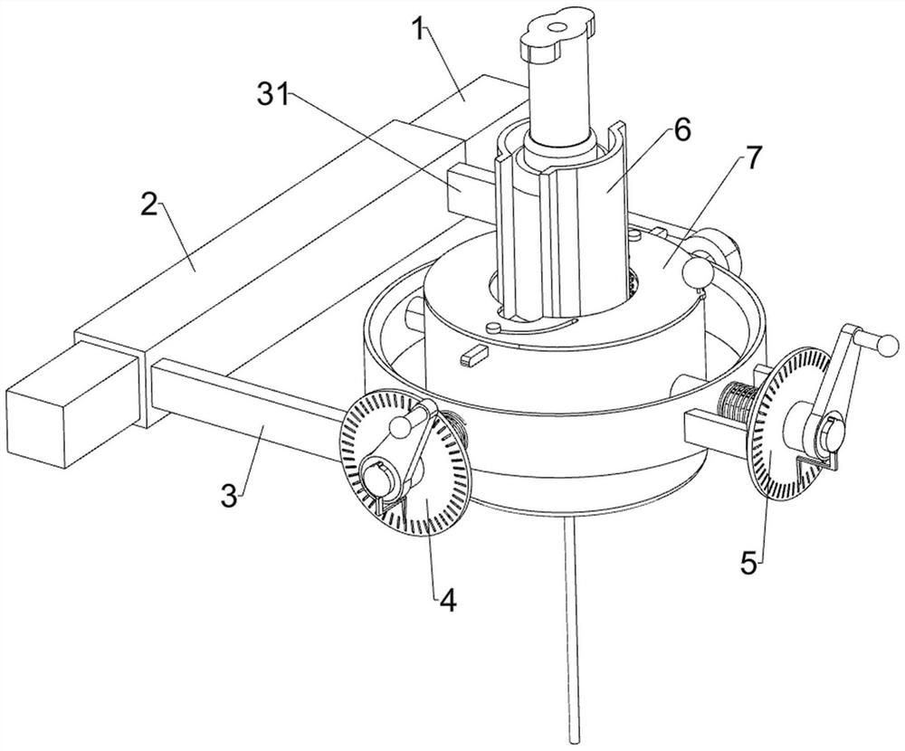
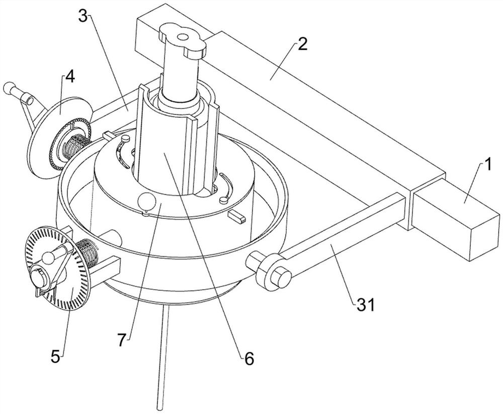
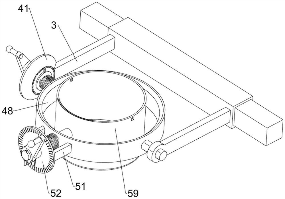
[0039] A guiding mechanism for CT puncture intervention, such asfigure 1 , figure 2 , image 3 , Figure 4 , Figure 5 , Image 6 , Figure 7 , Figure 8 , Figure 9 , Figure 10 As shown, it includes a guide rod 1, a first sliding rod 2, a first connecting bar 3, a second connecting bar 31, a first angle adjustment mechanism 4, a second angle adjustment mechanism 5, a puncture needle guiding mechanism 6 and a puncture needle fixing mechanism. Mechanism 7, the moving device of other positioning equipment is provided with a guide rod 1, the guide rod 1 is slidably connected with the first slide bar 2, and the first slide bar 2 is fixedly connected with the first connecting bar 3 and the second connecting bar 31 , the first connecting bar 3 is provided with a first angle adjustment mechanism 4, the first angle adjustment mechanism 4 is provided with a second angle adjustment mechanism 5, the first angle adjustment mechanism 4 and the second angle adjustment mechanism 5 a...

Embodiment 2

[0048] On the basis of Example 1, such as Figure 11 and Figure 12 As shown, it also includes a longitudinal locking mechanism 8, the longitudinal locking mechanism 8 is arranged on the sliding T-shaped frame 71, the longitudinal locking mechanism 8 is used to longitudinally fix the biopsy needle, and the longitudinal locking mechanism 8 includes a fixing bar 81 , sliding bar 82 and the fourth return spring 83, the bottom of the sliding T-shaped frame 71 is fixedly connected with a fixed bar 81, and the fixed bar 81 is slidably connected with a plurality of sliding bar 82 in a linearly distributed manner, and the sliding bar 82 is used In order to fix the biopsy needle to reduce its longitudinal shaking, a fourth return spring 83 is connected between the sliding locking rod 82 and the fixing bar 81 .

[0049] When the sliding T-shaped frame 71 and its upper device move toward each other, the fixed bar 81 and its upper device will also move toward each other. At this time, pa...

Embodiment 3

[0051] On the basis of Example 2, such as Figure 11 As shown, a laser positioning mechanism 9 is also included. The laser positioning mechanism 9 is arranged on the inner wall of the second rotating ring 59. The laser positioning mechanism 9 facilitates better positioning of the device. The laser positioning mechanism 9 includes a fixed frame 91 and a laser pointer 92 The inner wall of the second rotating ring 59 is symmetrically connected with a fixed frame 91 by bolts, the fixed frame 91 is provided with a laser pointer 92, and the laser pointer 92 is used to emit laser light.

[0052] Before the biopsy needle penetrates the human body, the laser pointer 92 will emit a laser beam. By observing the intersection of the laser beams, it is convenient to determine the height of the device from the human body, and at the same time, it is convenient to determine the insertion position of the biopsy needle, which realizes the convenience of updating the device. Well positioned for ...


PUM


Abstract

The invention relates to the technical field of medical instruments, in particular to a guiding mechanism for CT puncture intervention, which comprises a guide rod, a first sliding rod, a first connecting strip, a second connecting strip and the like, a guide rod is arranged on the moving device of other positioning equipment, a first sliding rod is connected to the guide rod in a sliding mode, and a first connecting strip and a second connecting strip are fixedly connected to the first sliding rod. Through the cooperation of the sliding clamping frame, the sliding clamping rod and the devices on the sliding clamping frame and the sliding clamping rod, the sliding clamping frame can transversely fix the biopsy needle, the sliding clamping rod can longitudinally fix the biopsy needle, the biopsy needle can be prevented from longitudinally shaking, the biopsy needle can also be prevented from transversely shaking, and the needle head is fully and effectively prevented from shifting; and the sampling of biopsy tissues can be smoothly completed while a patient is prevented from secondary injury.

Description

technical field [0001] The invention relates to the technical field of medical devices, in particular to a guiding mechanism for CT puncture intervention. Background technique [0002] CT puncture is a technique for biopsy of lesions under the guidance of CT scan positioning. The development of puncture technology not only improves the level of imaging diagnosis, but also provides important reference value for clinicians to choose treatment options. Puncture biopsy needles are widely used in the biopsy sampling of kidneys, liver, lungs, breasts and other organs. Under the positioning and guidance of CT color ultrasound or MRI, the puncture needle enters the specific position of the human body and passes through the puncture needle. Take out the tissues in the human body, and then make these tissues into specimens for special pathological examinations to determine whether the tissues themselves have lesions. [0003] Before the puncture, the biopsy needle needs to be adjuste...

Claims


Application Information

Patent Timeline
IPC IPC(8): A61B17/34A61B10/02A61B90/13
CPCA61B17/3403A61B10/0233A61B90/13A61B10/0283A61B2017/3405
Inventor 李长波王玉强袁天华
Owner HENAN UNIV HUAIHE HOSPITAL
Why Eureka
Try Eureka