Eureka AIR delivers breakthrough ideas for toughest innovation challenges, trusted by R&D personnel around the world.

Transmission device at production front end of transformer

A transmission device and transformer technology, applied in the field of automation, can solve the problems affecting the quality of the transformer, the complex outline of the transformer, and the inaccurate placement of the transformer, and achieve the effect of improving the efficiency of automated processing

Active Publication Date: 2022-03-11
JIANGSU ELECTRIC POWER CO +3
View PDF6 Cites 0 Cited by
  • Summary
  • Abstract
  • Description
  • Claims
  • Application Information

AI Technical Summary

Problems solved by technology

[0002] As an important electronic component in production and life, transformers play a vital role in voltage conversion, current conversion, impedance conversion, isolation, and voltage stabilization. Transformers are also basic equipment for power transmission and distribution, and are widely used in industries, In agriculture, transportation, urban communities and other fields, the demand for transformers is increasing year by year, and in order to meet the demand, automatic production methods are currently used to improve efficiency; but in the daily production process, due to the complex shape of the transformer, the transformer needs to be flipped during the production process Adjust the surface of the transformer, and the current flipping needs to be manually operated, which is inefficient and prone to inaccurate positioning due to human operation. On the other hand, it is difficult to guarantee the cleanliness of manual operation, and the operator will carry dust pollution to the transformer. , thus affecting the quality of the produced transformer

Method used


Image

  • Transmission device at production front end of transformer
  • Transmission device at production front end of transformer
  • Transmission device at production front end of transformer

Examples


Embodiment Construction

[0074] The technical solutions in the embodiments of the present invention will be clearly and completely described below in conjunction with the accompanying drawings in the embodiments of the present invention. Obviously, the described embodiments are only part of the embodiments of the present invention, not all of them. Based on the implementation methods in the present invention, all other embodiments obtained by persons of ordinary skill in the art without making creative efforts belong to the protection scope of the present invention.

[0075] In the drawings, the shapes and dimensions may be exaggerated for clarity, and the same reference numerals will be used throughout to designate the same or like parts.

[0076] Unless otherwise defined, the technical terms or scientific terms used herein shall have the usual meanings understood by those skilled in the art to which the present invention belongs. "First", "second" and similar words used in the specification of the p...


PUM


Abstract

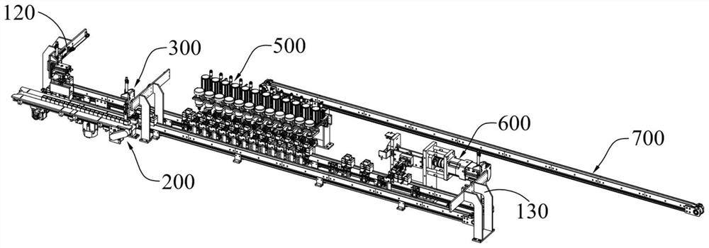
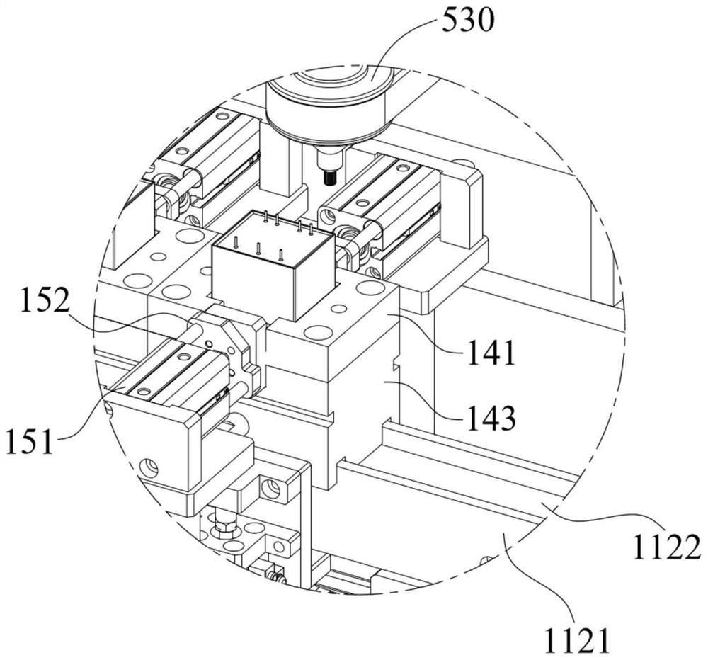
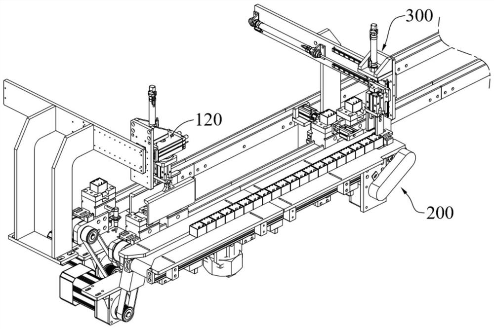
The invention relates to a transmission device at the front end of transformer production, which comprises a transmission assembly on which a carrier is circularly transmitted; the workpiece conveying line body is used for conveying the transformer element to the carrier of the conveying assembly; the blanking line body is used for transferring the transformer element on the carrier; wherein the transformer element comprises two corresponding side surfaces, namely a surface to be processed and a boss surface, the transformer element is transferred between the conveying assembly and the workpiece conveying line body through a feeding assembly, and a turnover mechanism is arranged between the discharging line body and the conveying assembly; the overturning mechanism comprises a grabbing component for rotating the transformer element on the carrier and an overturning driving part for driving the grabbing component to rotate; and after the grabbing component grabs the transformer element on the carrier, the transformer element is overturned to the discharging line body from the conveying assembly under the driving of the overturning driving part, and the to-be-machined face of the transformer element is overturned to the downward direction from the upward direction.

Description

technical field [0001] The invention relates to the technical field of automation, in particular to a transmission device at the front end of transformer production. Background technique [0002] As an important electronic component in production and life, transformers play a vital role in voltage conversion, current conversion, impedance conversion, isolation, and voltage stabilization. Transformers are also basic equipment for power transmission and distribution, and are widely used in industries, In agriculture, transportation, urban communities and other fields, the demand for transformers is increasing year by year, and in order to meet the demand, automatic production methods are currently used to improve efficiency; but in the daily production process, due to the complex shape of the transformer, the transformer needs to be flipped during the production process Adjust the surface of the transformer, and the current flipping needs to be manually operated, which is inef...

Claims


Application Information

Patent Timeline
Patent Type & Authority Applications(China)
IPC IPC(8): B65G47/248B65G47/52
CPCB65G47/248B65G47/52B65G2201/0214
Inventor 于峰于沐宇
Owner JIANGSU ELECTRIC POWER CO
Why Eureka
Eureka Blog
Learn More