
Constant-current power supply circuit for plasma torch and plasma torch system

A technology of plasma torch and constant current power supply, which is applied in the direction of control/regulation system, electrical components, and adjustment of electrical variables, etc., which can solve problems such as large ripple and large output inductance value, achieve optimal operation, reduce fluctuation value, and meet The effect of low pulsation requirements

Pending Publication Date: 2022-03-08
新奥(天津)能源技术有限公司
View PDF5 Cites 0 Cited by
  • Summary
  • Abstract
  • Description
  • Claims
  • Application Information

AI Technical Summary

Problems solved by technology

[0003] However, in the currently used three-phase bridge fully-controlled rectification structure, the switching frequency adjusted by the circuit is six times the power frequency. This frequency is low, and the required output inductance value is larger, and the output current will be accompanied by six times the power frequency. larger ripple
In addition, the current high-frequency switching power supply rectification output structure, the corresponding switching frequency of the circuit can be designed to the high-frequency band, but the output of the constant current source is realized by the output inductor, and the output current inevitably has a ripple at the same frequency as the switching frequency. Ripple current, the fluctuation value of this ripple current can reach more than 10% of the average value of the output current

Method used


Image

  • Constant-current power supply circuit for plasma torch and plasma torch system
  • Constant-current power supply circuit for plasma torch and plasma torch system
  • Constant-current power supply circuit for plasma torch and plasma torch system

Examples


Embodiment Construction

[0035] In order to more clearly understand the above objects, features and advantages of the present disclosure, the solutions of the present disclosure will be further described below. It should be noted that, in the case of no conflict, the embodiments of the present disclosure and the features in the embodiments can be combined with each other.

[0036] In the following description, many specific details are set forth in order to fully understand the present disclosure, but the present disclosure can also be implemented in other ways than described here; obviously, the embodiments in the description are only some of the embodiments of the present disclosure, and Not all examples.

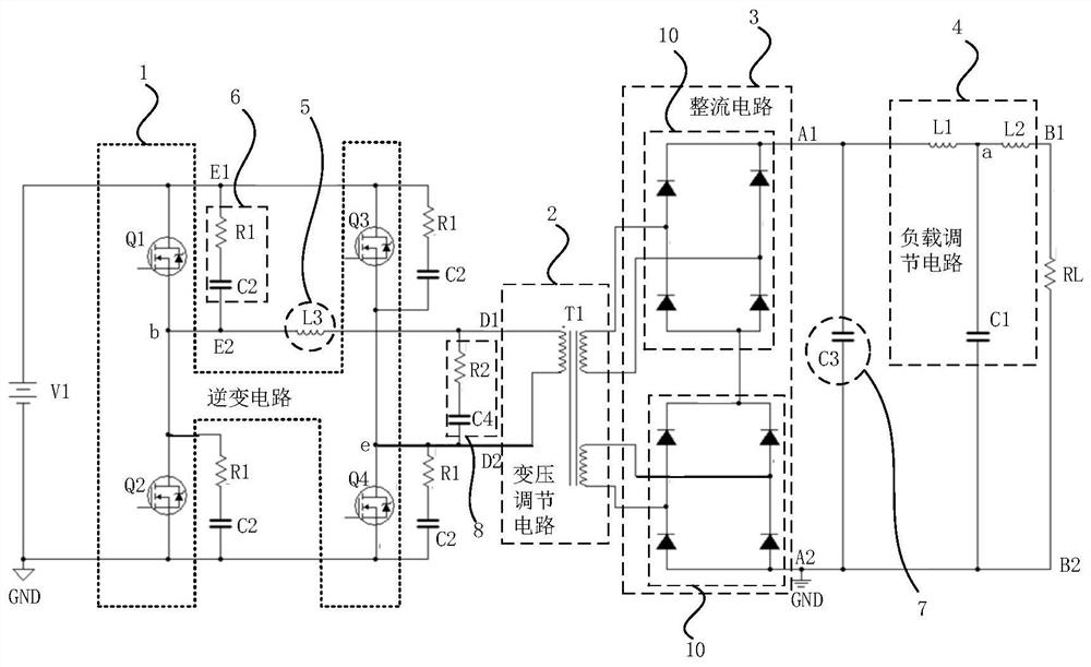
[0037] figure 1 A schematic structural diagram of a constant current power supply circuit for a plasma torch provided by an embodiment of the present disclosure. Such as figure 1 As shown, the constant current power supply circuit for the plasma torch includes a power supply V1, an inverter ci...


PUM


Abstract

The invention relates to a constant-current power supply circuit for a plasma torch and a plasma torch system, and the constant-current power supply circuit for the plasma torch comprises an inverter circuit which is used for converting a direct-current power supply signal outputted by a power supply into an alternating-current power supply signal; the voltage transformation adjusting circuit is used for adjusting and outputting the voltage of the alternating current power supply signal; the rectifying circuit is used for converting the voltage-regulated alternating-current power supply signal output by the voltage transformation regulating circuit into a direct-current power supply signal; the load adjusting circuit is used for outputting a constant-current power supply signal to a plasma torch load; the load adjusting circuit comprises a first inductor, a second inductor and a first capacitor, the first inductor and the second inductor are connected in series between the positive output end of the rectifying circuit and the positive end of the plasma torch load, and the first capacitor is connected in series between the series connection node of the first inductor and the second inductor and the negative end of the plasma torch load. According to the technical scheme, the fluctuation value of the output current of the power supply circuit is effectively reduced.

Description

technical field [0001] The disclosure relates to the technical field of electronic circuits, in particular to a constant current power supply circuit for a plasma torch and a plasma torch system. Background technique [0002] During the operation of the plasma torch, it is particularly important to be able to precisely control the plasma. The control process of the plasma not only affects the temperature and velocity of the hot flow gas, but also affects the distribution of the plasma. Generally, in order to stabilize the application effect, the plasma must have stable parameters, which requires the plasma torch power supply to have a stable output current. The fluctuation of the power supply affects the fluctuation of the arc. In order to eliminate the adverse effect of the power supply on the arc fluctuation, the power frequency ripple of the output current of the power supply should be as small as possible. [0003] However, in the currently used three-phase bridge fully...

Claims


Application Information

Patent Timeline
Patent Type & Authority Applications(China)
IPC IPC(8): H02M1/14H02M3/335H02M3/24
CPCH02M1/14H02M3/33569H02M3/24
Inventor 李明高锐陈培培梁海军
Owner 新奥(天津)能源技术有限公司
Learn More