
Air suspension chassis

An air suspension and chassis technology, applied in conveyors, transportation and packaging, non-mechanical conveyors, etc., can solve the problems of flexible airbag overload, complex manufacturing process, poor structural reliability and durability, and achieve low travel resistance Effect

Pending Publication Date: 2022-03-08
SHENZHEN FENGYANG SCI & TECH IND CO LTD
View PDF0 Cites 0 Cited by
  • Summary
  • Abstract
  • Description
  • Claims
  • Application Information

AI Technical Summary

Problems solved by technology

In some special fields, the load-bearing surface can be in an ideal flat state. At this time, it is awkward to use the flexible airbag to carry it. Especially in the scene of carrying light weight objects, the flexible airbag will present problems such as overload, large air consumption, and failure to integrate.
Moreover, the existing air suspension device has a complex manufacturing process and poor structural reliability and durability

Method used


Image

  • Air suspension chassis
  • Air suspension chassis
  • Air suspension chassis

Examples


Embodiment 1

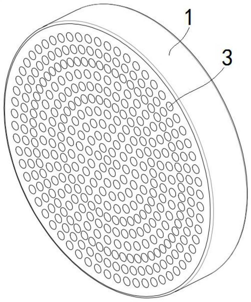
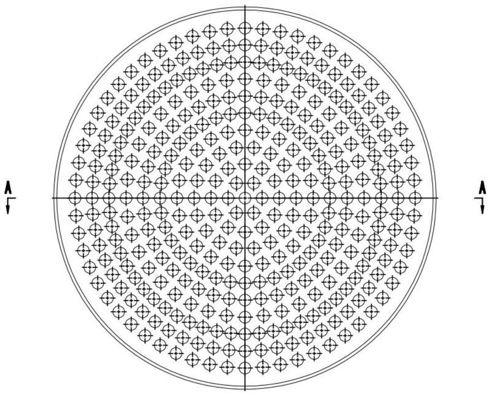
[0033] See attached Figure 1-3 It is a schematic diagram of the overall and partial structure of an embodiment of the present invention, and the present invention specifically discloses an air suspension chassis that slides on a horizontal bearing surface (not shown in the figure) and The air pump (not shown in the figure) is air-connected, including:

[0034] The chassis body 1, the chassis body 1 in this embodiment is in the shape of a disc. Of course, it can also be other shapes, such as rectangle, polygon or a combination of several shapes. One side plate surface of the chassis body 1 is fixed to the load, and the fixing method may be bonding, welding, clamping, bolt connection or other connection methods. An air inlet 2 connected to the air pump is opened in the center of the chassis body 1, and an air outlet connected to the air inlet 2 is provided on the side plate of the chassis body 1 away from the load, and an air outlet of the air outlet is opened on the chassis ...

Embodiment 2

[0038] See attached Figure 4-6 It is a schematic diagram of the overall and partial structure of an embodiment of the present invention. The difference between this embodiment and Embodiment 1 is that: on the side plate surface of the chassis body 1 where the air outlet is provided, it is radially uniform with its axis as the center. The cloth is provided with a plurality of through grooves-14, and the plurality of through grooves-14 are all communicated with the air inlet 2, and the air outlet in the present embodiment includes a plurality of annular air outlet grooves-5, and the plurality of air outlet grooves-5 are all connected to the chassis. The body 1 is coaxially arranged, and a plurality of outlet slots 15 communicate with the inlet holes 2 through a plurality of through slots 14 .

Embodiment 3

[0040] See attached Figure 7-9 It is a schematic diagram of the overall and partial structure of an embodiment of the present invention. The difference between this embodiment and Embodiment 1 is that the air outlet in this embodiment includes an air outlet 2 6 and an annular air outlet groove 2 7, and the air outlet 2 6 There are multiple air outlet slots 2 and 7 respectively, and the multiple air outlet slots 7 are coaxially arranged with the chassis body 1. The multiple air outlet holes 6 are all limited to the inside of the air outlet slot 7 with the smallest diameter and arranged uniformly. The inside of the body 1 is integrally formed with an air cavity 28 with a circular cross section. The bottom wall of each air outlet groove 27 is provided with a plurality of through holes 15 communicating with the air cavity 28. The plurality of air outlet holes 26 are all connected to each other. It communicates with the second air cavity 8, and the air inlet 2 communicates with th...


PUM


Abstract

The invention discloses an air suspension chassis which comprises a chassis body, a load is provided with the chassis body for bearing the load, the chassis body is provided with an air inlet hole communicated with an air pump, and one end face of the chassis body is provided with an air outlet part communicated with the air inlet hole; the end face, provided with the air outlet part, of the chassis body is parallel to the horizontal bearing face and can be separated through air. The chassis body is provided with the air inlet hole and the air outlet part communicated with the air inlet hole, and when the chassis body is applied, a layer of air cushion film can be formed between the end face, provided with the air outlet part, of the chassis body and the horizontal bearing face, so that extremely low advancing resistance exists between the chassis body and the horizontal bearing face; the chassis body is simple in structure, ingenious in design, low in machining and manufacturing cost, energy-saving and practical while safety and reliability are guaranteed, high practical application value is achieved, and the low-resistance moving requirement of small objects is widely met.

Description

technical field [0001] The invention relates to the technical field of air suspension, and more specifically relates to an air suspension chassis. Background technique [0002] Traditional air suspension devices generally use flexible materials such as rubber as the main medium in the form of airbags, and are widely used in the movement and handling of heavy objects on ordinary bearing surfaces. In some special fields, the load-bearing surface can be in an ideal flat state. At this time, it is awkward to use the flexible airbag to carry it. Especially in the scene of carrying light weight objects, the flexible airbag will present problems such as overload, large air consumption, and failure to integrate. Moreover, the existing air suspension device has a complex manufacturing process and poor structural reliability and durability. [0003] Therefore, how to provide an air suspension chassis that can overcome the above-mentioned problems is an urgent problem to be solved by ...

Claims


Application Information

Patent Timeline
Patent Type & Authority Applications(China)
IPC IPC(8): B65G54/00
CPCB65G54/00B65G2201/0223
Inventor 叶祥县季国强邹家龙张明东叶天禄叶志炫姚松
Owner SHENZHEN FENGYANG SCI & TECH IND CO LTD
Learn More