
Automatic shaping machine for metal corrugated pipe

A metal bellows and shaping machine technology, which is applied in the field of metal bellows automatic shaping machines and bellows shaping equipment, can solve problems such as difficult to meet bellows, impact or jamming, and insufficient overall rigidity.

Active Publication Date: 2022-03-08
AEROSUN CORP
View PDF17 Cites 0 Cited by
  • Summary
  • Abstract
  • Description
  • Claims
  • Application Information

AI Technical Summary

Problems solved by technology

However, practice shows that this technical solution still has the following deficiencies: firstly, the rotating shaft is in an unsupported state at the right end, and the overall rigidity is insufficient, which will affect the shaping quality of the bellows product; secondly, the axial pressing device of the die is The rotation limit of the screw nut adopts the locking wrench fixed on the mobile trolley, and the shape of the nut itself makes it easy to cause impact or jamming due to the interference of the angle of fit when the wrench is interfitted, affecting normal operation
In addition, the analysis shows that the upper screw shaft and the lower screw shaft are meshed with gears, and the rotation speed ratio is fixed, which is difficult to meet the requirement that the rotation speed ratio of the inner axis and the outer axis of the corrugated tube blank varies with the thickness of the tube blank. It is easy to cause the bellows to shake

Method used


Image

  • Automatic shaping machine for metal corrugated pipe
  • Automatic shaping machine for metal corrugated pipe
  • Automatic shaping machine for metal corrugated pipe

Examples


Embodiment Construction

[0030] The technical solutions in this embodiment will be further described in detail below in conjunction with the accompanying drawings.

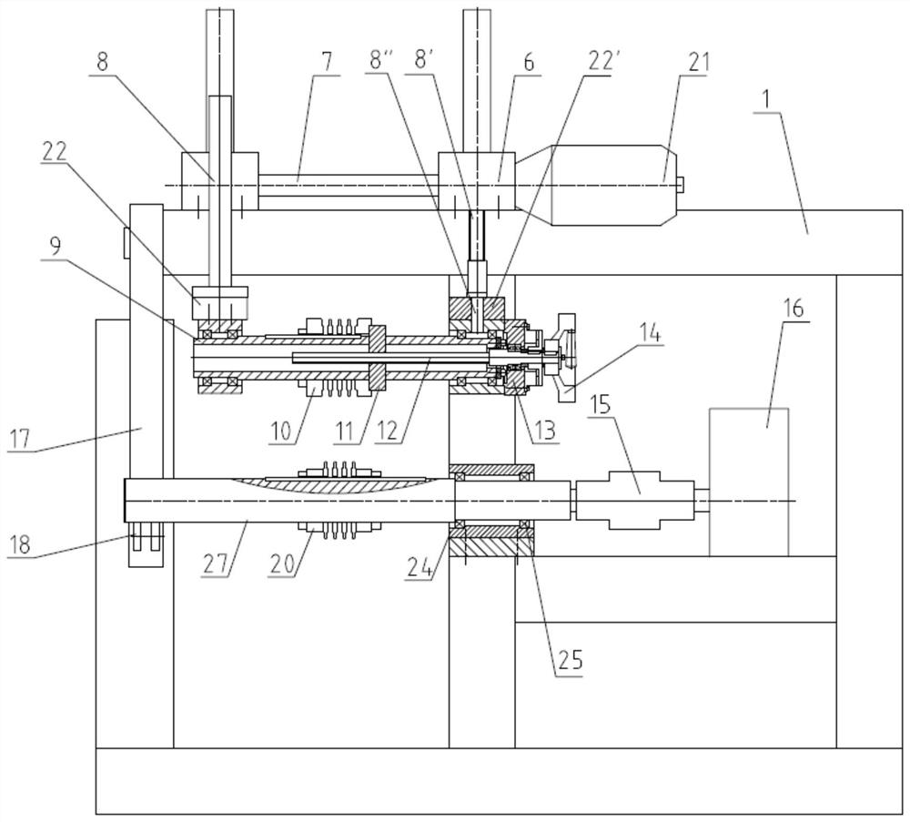
[0031] This embodiment is a metal bellows multi-wave automatic shaping machine as bellows shaping equipment, and its specific structure is as follows image 3 and Figure 4 As shown, the main motor 16 containing the speed reducer is arranged at the bottom of the frame 1 of the frame structure, the output shaft of the main motor is connected to the horizontal driving shaft 27 through a coupling 15, and the driving shaft 27 is equipped with clamping blocks at both ends and The active shaping die 20 is composed of distributing die sheets at intervals in the middle, and under the constraint of the feather key structure, the active rotating shaft 27 and the active shaping die 20 constitute a circumferentially moving pair constrained by the circumferential direction. The upper part of the frame 1 is equipped with a hoist 6 driven by a hoist mo...


PUM


Abstract

The invention relates to corrugated pipe shaping equipment, and belongs to the field of machine manufacturing. A main motor at the lower part of a rack of the equipment is in transmission connection with a driving rotating shaft provided with a driving sizing die; the lower end of a guide pillar of the elevator is provided with a driven rotating shaft with a driven sizing die; one end of the driving rotating shaft is supported in a bearing mounted on the rack; the telescopic end of a telescopic driving device hinged to the rack is hinged to the middle of a rotating arm, and the upper end of the rotating arm is hinged to the rack. When the telescopic driving device is in the stretching position, the other end of the driving rotating shaft is supported on a supporting roller at the lower part of the rotating arm; and when the telescopic driving device is in the retraction position, the supporting roller at the lower part of the rotating arm leaves the driving rotating shaft. After the workpiece supporting device is adopted, as long as the telescopic driving device is controlled to be located at the stretching or retracting position according to needs, stable supporting can be achieved, and workpiece sleeving is facilitated.

Description

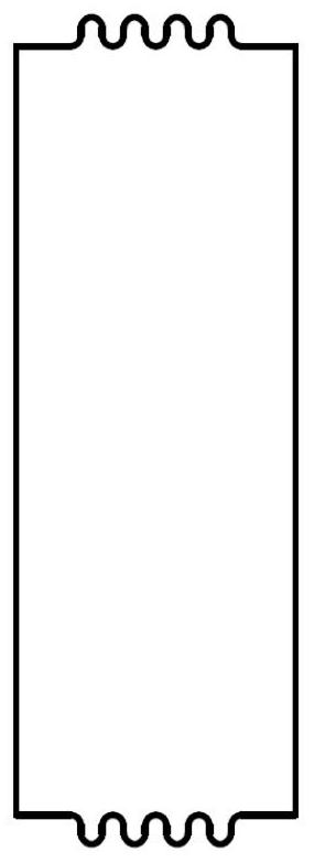
technical field [0001] The invention relates to a bellows shaping device, in particular to an automatic metal bellows shaping machine, which belongs to the field of machinery manufacturing. Background technique [0002] Metal bellows are elastic components widely used in aviation, military, electric power, chemical and other industries. The typical process of the corrugated pipe manufacturing process is to reshape with the help of corrugated pipe shaping equipment after rough wave processing (see figure 1 and figure 2 ). [0003] According to the applicant's knowledge, traditional corrugated tube shaping equipment generally has disadvantages such as low shaping efficiency (single wave shaping), difficult to control precision, low degree of automation, complex structure, and inconvenient operation. For this reason, the Chinese patent application number CN201910977242.9 discloses a metal bellows automatic shaping machine, which consists of a bed, a main motor, a lifting el...

Claims


Application Information

Patent Timeline
IPC IPC(8): B21D3/16
CPCB21D3/16Y02P70/10
Inventor 李缓缓黄静白玉
Owner AEROSUN CORP
Learn More