Method and system for protecting direct current transmission line
A technology for DC transmission lines and protection systems, applied in emergency protection circuit devices, short-circuit tests, electrical components, etc., can solve problems such as long time to judge faults, unreliable fault distinction, and inability to protect the full length of the line, so as to save protection time , short protection time, reliable detection effect
- Summary
- Abstract
- Description
- Claims
- Application Information
AI Technical Summary
Problems solved by technology
Method used
Image
Examples
Embodiment 1
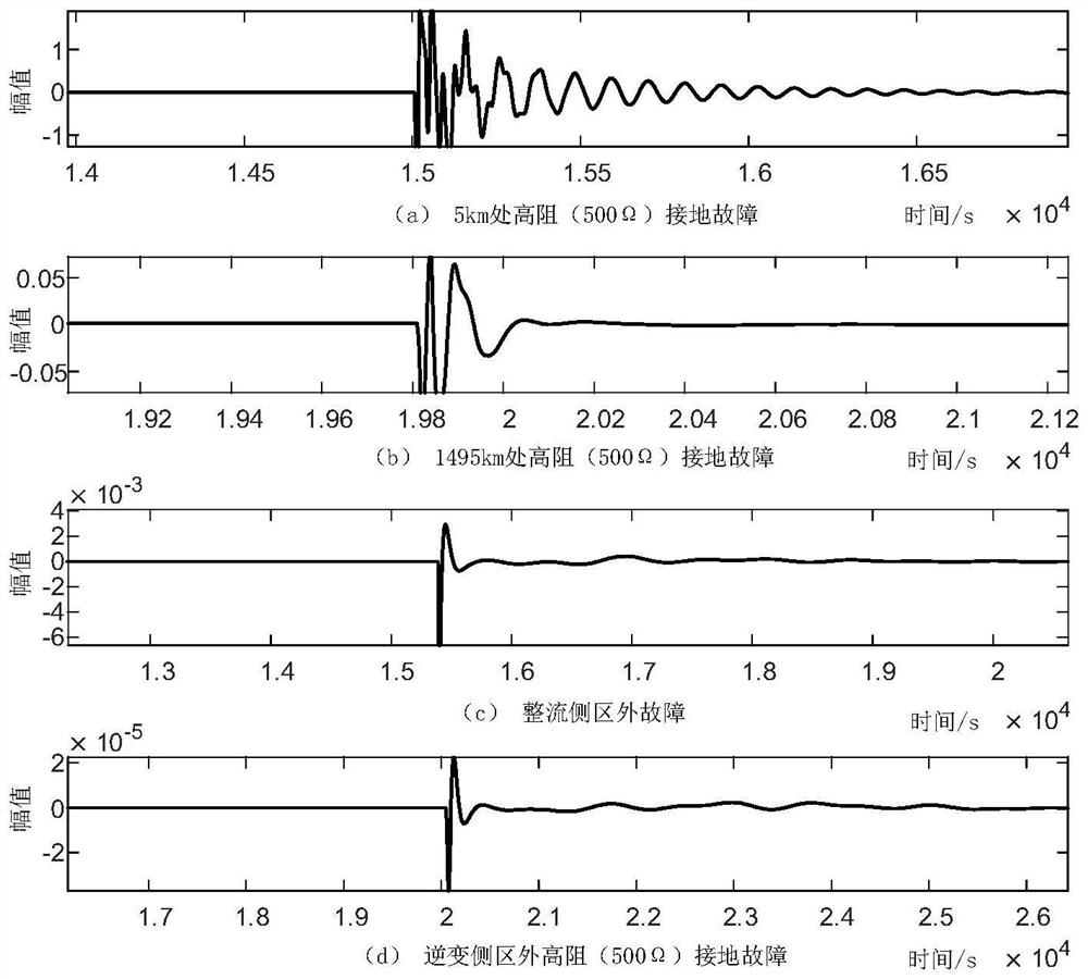
[0061] Example 1: First, build a DC transmission line model in PSCAD / EMTDC. The line length is 1500km, the voltage level is ±800kV, and the sampling frequency is 1MHz. The rectifier side external faults are set respectively, and the high-resistance (500Ω) ground fault at 5km is 1495km. There are four cases of high-resistance (500Ω) ground fault and high-resistance (500Ω) ground fault outside the inverter side area.
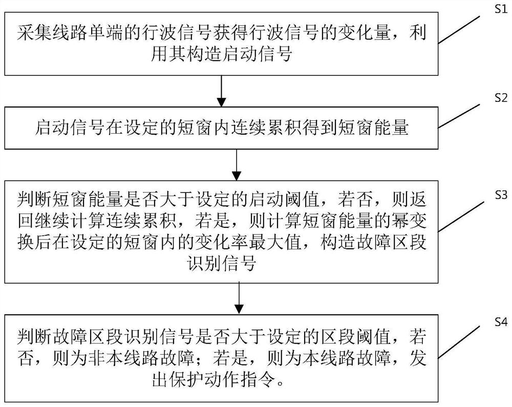
[0062] like figure 1 As shown, a DC transmission line protection method, the specific steps are:
[0063] Step1: Collect the traveling wave signal at the single end of the line to obtain the variation of the traveling wave signal, and use it to construct the start signal.
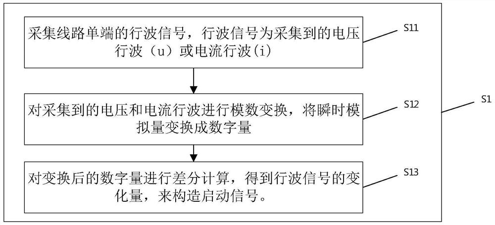
[0064] like figure 2 As shown, the specific steps of Step1 are:
[0065] Step1.1: Collect the traveling wave signal of the single end of the line, and the traveling wave signal is the collected voltage traveling wave u or current traveling wave i. The single end is the first end or the sec...
Embodiment 2
[0098] Example 2: First, build a DC transmission line model in PSCAD / EMTDC. The line length is 1500km, the voltage level is ±800kV, and the sampling frequency is 200kHz. Set the metal grounding fault outside the rectifier side and the metal grounding outside the inverter side. Fault, high resistance (500Ω) ground fault outside the rectifier side, high resistance (500Ω) ground fault outside the inverter side, high resistance (500Ω) ground fault at 5km, high resistance (500Ω) fault at 1200km, high resistance (500Ω) at 1495km There are eight cases of high resistance (500Ω) fault between poles and high resistance (500Ω) ground fault at 1495km.
[0099] The specific implementation steps are:
[0100] Step1: Collect the traveling wave signal at the single end of the line to obtain the variation of the traveling wave signal, and use it to construct the start signal.
[0101] Step1 The specific steps are:
[0102] Step1.1: Collect the traveling wave signal of the single end of the l...
Embodiment 3
[0128] like Figure 9 As shown, a DC transmission line protection system includes:
[0129] The numerical calculation module is used to obtain the variation of the traveling wave signal and construct the start signal. Calculate the short-window energy of the start signal within the set short-window I. Calculate the absolute value of the short-window energy. Computes the power transform of the absolute value of the short-window energy. Calculate the maximum value of the change rate of the absolute value of the short-window energy within the set short-window II, and construct the fault section identification signal.
[0130] The logic judgment module is used to judge whether the absolute value of the short-window energy is greater than the set startup threshold. If not, continue to execute the short-window energy; if so, judge whether the absolute value of the short-window energy is greater than 1; The absolute value of the energy is multiplied by a coefficient to make its v...
PUM
 Abstract
Description
Claims
Application Information
 - R&D
- Intellectual Property
- Life Sciences
- Materials
- Tech Scout
- Unparalleled Data Quality
- Higher Quality Content
- 60% Fewer Hallucinations
Browse by: Latest US Patents, China's latest patents, Technical Efficacy Thesaurus, Application Domain, Technology Topic, Popular Technical Reports.
© 2025 PatSnap. All rights reserved.Legal|Privacy policy|Modern Slavery Act Transparency Statement|Sitemap|About US| Contact US: help@patsnap.com


