Novel insulator curing equipment
A technology for curing equipment and insulators, applied to insulators, electrical components, circuits, etc., can solve problems such as deformation, single solidification of insulator cores, and unstable placement of insulators, so as to improve the curing quality, improve the scope of application, and increase the scope of clamping. Effect
- Summary
- Abstract
- Description
- Claims
- Application Information
AI Technical Summary
Problems solved by technology
Method used
Image
Examples
Embodiment 1
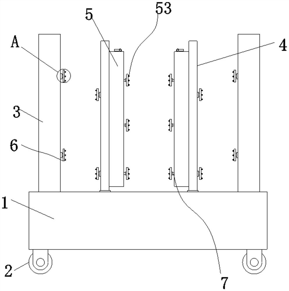
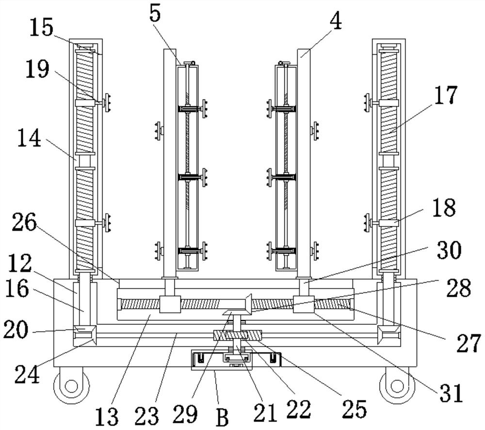
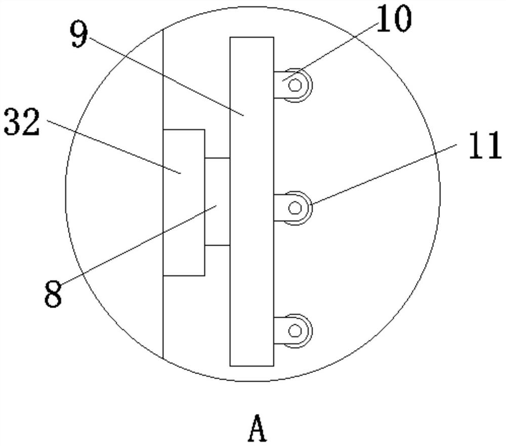
[0033] Embodiment one, by Figure 1 to Figure 6Given, the present invention comprises a base 1, the bottom of the base 1 is symmetrically provided with moving wheels 2, the top of the base 1 is symmetrically provided with support plates 3 on both sides, and the top of the base 1 is symmetrically provided with a support plate between the two support plates 3. The movable plate 4 is connected by a distance adjustment mechanism between the two movable plates 4. By the design of the distance adjustment mechanism, it is convenient to realize the movement of the movable plate 4, and then it is convenient to make the clamping part 2 53 on the movable plate 4 and the support plate 3 The clamping part 16 clamps the inner core of the insulator, and then can realize the clamping of the inner core of the insulator with different sizes, thereby improving the use range of the device, and improving the stability for the curing of the insulator. Two movable plates 4 A fixed plate 5 is arrange...
Embodiment 2
[0036] Embodiment two, on the basis of embodiment one, by figure 2 and image 3 Given, the height adjustment mechanism comprises a rotating shaft 16, a screw barrel 17, a threaded block 18, a slide rod 19 and a bevel gear 120, and the inside of the accommodation groove 3 14 is provided with a rotating shaft 16, and one end of the rotating shaft 16 extends To the inside of the accommodation groove one 12, the bottom end of the rotating shaft 16 is provided with a bevel gear one 20, and the outside of the rotating shaft 16 is fixedly connected with two screw tubes 17, and the outer thread of the screw tube 17 is connected with a threaded block one. 18. One end of the threaded block one 18 is provided with a slide bar one 19, and the adjacent sides of the two support plates 3 are provided with a slot one 15 communicating with the receiving groove three 14, and the slide bar one 19 runs through the slot one 15 and extends to the outside of the receiving groove three 14, and one ...
Embodiment 3
[0038] Embodiment three, on the basis of embodiment one, by figure 2 and Figure 4 Provide, the driver comprises rotating shaft 21, turbine one 22, power transmission shaft 23, bevel gear two 24 and worm barrel 25 and bevel gear four 29 and fixed group, the inside of accommodating groove one 12 is provided with rotating shaft 21, and rotating shaft One end of 21 is connected with fixed group, and one end of rotating shaft 21 extends to the inwall of accommodation groove two 13, and rotating shaft 21 is provided with turbine one 22 and bevel gear four 29, and turbine one 22 is positioned at the inside of accommodation groove one 12, and the cone Bevel gear four 29 is positioned at the inside of worm screw two 43, and the inside of accommodating groove one 12 is equipped with transmission shaft 23, and transmission shaft 23 is symmetrically provided with bevel gear two 24 that meshes with bevel gear one 20, and the middle of transmission shaft 23 The position is fixedly connec...
PUM
 Abstract
Description
Claims
Application Information
 - R&D
- Intellectual Property
- Life Sciences
- Materials
- Tech Scout
- Unparalleled Data Quality
- Higher Quality Content
- 60% Fewer Hallucinations
Browse by: Latest US Patents, China's latest patents, Technical Efficacy Thesaurus, Application Domain, Technology Topic, Popular Technical Reports.
© 2025 PatSnap. All rights reserved.Legal|Privacy policy|Modern Slavery Act Transparency Statement|Sitemap|About US| Contact US: help@patsnap.com


