
Backlight module and display device

A backlight module and backlight technology, applied in optics, nonlinear optics, instruments, etc., can solve the problems that the shadow effect cannot be further improved, increase the complexity of backlight board and module production, etc., and achieve good display effect , enhance viewing taste, and improve the effect of brightness imbalance

Pending Publication Date: 2022-03-04
HUIZHOU CHINA STAR OPTOELECTRONICS TECHNOLOGY CO LTD
View PDF5 Cites 1 Cited by
  • Summary
  • Abstract
  • Description
  • Claims
  • Application Information

AI Technical Summary

Problems solved by technology

However, the above methods have their own defects: reducing the distance between the lamp bead and the edge is limited due to the limited range, so it will be closer to the critical value as the pitch of the designed light-emitting unit (pitch) decreases, so that the effect of improving the shadow cannot be further improved; modify The patchwork design increases the complexity of backlight panels and modules; the added reflective sheet will increase the thickness in the patchwork area, which will have a certain blocking effect on the above and adjacent light-emitting units. The effect is greater for light-emitting units (such as ~100um flip chips)

Method used


Image

  • Backlight module and display device
  • Backlight module and display device
  • Backlight module and display device

Examples


Embodiment Construction

[0027] The implementation of the present invention will be described in detail below in conjunction with the drawings and examples, so as to fully understand and implement the process of how to apply technical means to solve technical problems and achieve technical effects in the present invention. It should be noted that, as long as there is no conflict, each embodiment and each feature in each embodiment of the present invention can be combined with each other, and the formed technical solutions are all within the protection scope of the present invention.

[0028] Also, in the following description, for purposes of explanation, numerous specific details are set forth in order to provide a thorough understanding of embodiments of the invention. It will be apparent, however, to one skilled in the art, that the invention may be practiced without the specific details of this example or in the particular manner described.

[0029] The invention provides a backlight module and a ...


PUM


Abstract

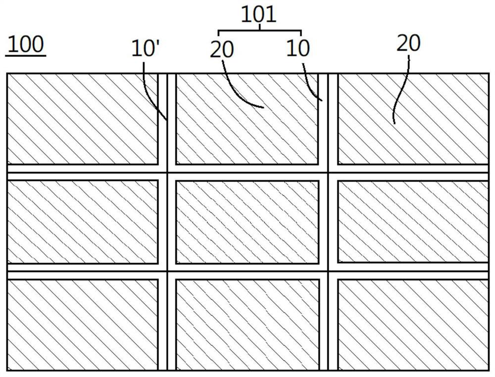
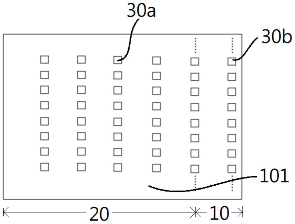
The invention discloses a backlight module and a display device applying the backlight module, the backlight module is formed by splicing a plurality of backlight lamp panels, each of the plurality of backlight lamp panels comprises a body area and a splicing seam area located on the peripheral side of the body area, the abutted seam area is defined as an area adjacent to an abutted seam between every two adjacent backlight lamp panels in the plurality of backlight lamp panels; the backlight lamp panel is characterized in that the backlight lamp panel comprises a plurality of first light-emitting units, a plurality of second light-emitting units and a plurality of second light-emitting units, the first light-emitting units are arranged in the body area, the splicing seam area is arranged in the body area, the second light-emitting units are arranged in the splicing seam area, the first light-emitting units and the second light-emitting units are arranged in a matrix mode, and under the same area, the brightness of the body area is lower than that of the splicing seam area.

Description

technical field [0001] The invention relates to the field of display technology, in particular to a backlight module with uniform visual brightness. Background technique [0002] The backlight in the existing large-size liquid-crystal display (LCD) is generally formed by splicing multiple backlight panels, and shadows are prone to appear at the joints (that is, joints) of adjacent backlight panels, resulting in backlight The brightness of the board body area and the seam area is uneven, which is due to the uneven alignment, uneven seam line or reduced reflectivity, which causes the brightness of the seam area of ​​the backlight panel to decrease. In order to improve the shadow phenomenon in the patchwork area of ​​the backlight panel, known methods include reducing the distance from the edge of the light-emitting unit (such as a small lamp bead) on the backlight panel, optimizing the patchwork design, and adding additional reflectors to the patchwork area. film etc. Howeve...

Claims


Application Information

Patent Timeline
Patent Type & Authority Applications(China)
IPC IPC(8): G02F1/13357
CPCG02F1/133611G02F1/133603G02F1/133606G02F1/133607G02F1/133613G02F1/13336
Inventor 陈东子王娇
Owner HUIZHOU CHINA STAR OPTOELECTRONICS TECHNOLOGY CO LTD
Learn More