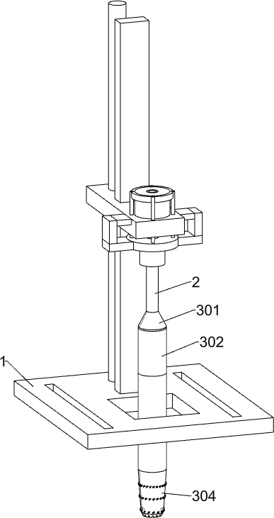
Sampling device for detection of mountain structure for laying oil pipelines
A technology for structural detection and oil pipelines, applied in the field of geological exploration, can solve the problems that mountain samples cannot be taken out, mountain samples cannot be separated and disconnected, etc.
- Summary
- Abstract
- Description
- Claims
- Application Information
AI Technical Summary
Problems solved by technology
Method used
Image
Examples
Embodiment 1
[0034] A kind of sampling device for the detection of mountain structure for laying oil pipelines, such as Figure 1-Figure 10 and Figure 14-Figure 15 As shown, it includes a driving device 1, a drill pipe 2, a protective shell 301, a first shell 302, a first circular plate 303, a second shell 304, a circular shell 305, a second circular plate 306, a water guide pipe 307, and a trigger mechanism. , a cutting mechanism, a sealing mechanism and a reset mechanism, the drill pipe 2 is installed on the front of the driving device 1, and the driving device 1 is a mechanical device used to rotate and move down the drill pipe 2, and the protective shell 301 is fixed on the drill The lower end of the rod 2, the lower end of the protective shell 301 is fixedly connected with the first shell 302, and the upper inner surface of the first shell 302 is fixedly connected with the first circular plate 303, and the first circular plate 303 cooperates with the protective shell 301 to form a wa...
Embodiment 2
[0037] On the basis of Example 1, such as Figure 4 and Figure 5 As shown, the trigger mechanism includes a first connecting rod 308, a fixed ring 309, a first rotating ring 310, a spring 311, a moving ring 312, a first support frame 313, a pole 314, a square shell 315, a sliding bar 316 and a first Extension spring 317, the front and rear two parts of the second circular plate 306 are slidingly connected with the first connecting rod 308 respectively, the lower ends of the two first connecting rods 308 are fixedly connected with the fixed ring 309, and the lower side of the fixed ring 309 is rotatably connected with the first connecting rod. The rotating ring 310, the lower parts of the outer surfaces of the two first connecting rods 308 are respectively ringed with springs 311, and the two ends of the springs 311 are fixedly connected to the second circular plate 306 and the fixed ring 309 respectively, and the upper ends of the two first connecting rods 308 Fixedly connec...
Embodiment 3
[0046] On the basis of Example 2, such as Figure 11-Figure 13 As shown, it also includes an extruding mechanism, and the extruding mechanism includes an inner gear ring 501, a third connecting rod 502, a rack 503, a first support seat 504, a second support seat 505, a first rotating rod 506, a first The gear 507, the first bevel gear 508, the second rotating rod 509, the second bevel gear 510, the second gear 511, the rotating wheel 512 and the guide ring 513, the inner gear ring 501 is rotatably connected to the upper side of the second circular plate 306, The front and rear parts of the outer side of the inner gear ring 501 are respectively fixed with third connecting rods 502, and the front and rear parts of the second circular plate 306 are respectively provided with arc-shaped slide grooves, and the two third connecting rods 502 are respectively slidably connected to the second In the two arc-shaped chutes of the circular plate 306, the rear side of the first connecting ...
PUM
 Abstract
Description
Claims
Application Information
 - R&D Engineer
- R&D Manager
- IP Professional
- Industry Leading Data Capabilities
- Powerful AI technology
- Patent DNA Extraction
Browse by: Latest US Patents, China's latest patents, Technical Efficacy Thesaurus, Application Domain, Technology Topic, Popular Technical Reports.
© 2024 PatSnap. All rights reserved.Legal|Privacy policy|Modern Slavery Act Transparency Statement|Sitemap|About US| Contact US: help@patsnap.com


