Method, device and equipment for distributing propulsive force of synchronous pushing and splicing system of shield tunneling machine and medium

A distribution method and propulsion technology, which are applied in the field of shield tunnel construction technology and equipment, can solve the problems of inability to realize the distribution of the propulsion force of the remaining oil cylinders, and achieve the reduction of power loss, shield attitude and propulsion speed assurance, and accurate adjustment. Effect

Pending Publication Date: 2022-03-04
CHINA RAILWAY ENGINEERING EQUIPMENT GROUP CO LTD
View PDF0 Cites 3 Cited by
  • Summary
  • Abstract
  • Description
  • Claims
  • Application Information

AI Technical Summary

Problems solved by technology

[0005] In view of the above-mentioned problems in the prior art, the purpose of this paper is to provide a propulsion distribution method, device, equipment and medium for the synchronous pushing and assembly system of the shield machine, so as to solve the problem that the remaining oil cylinders cannot be retracted and assembled in the prior art. Problems of propulsion distribution and calculation of remaining cylinder propulsion

Method used

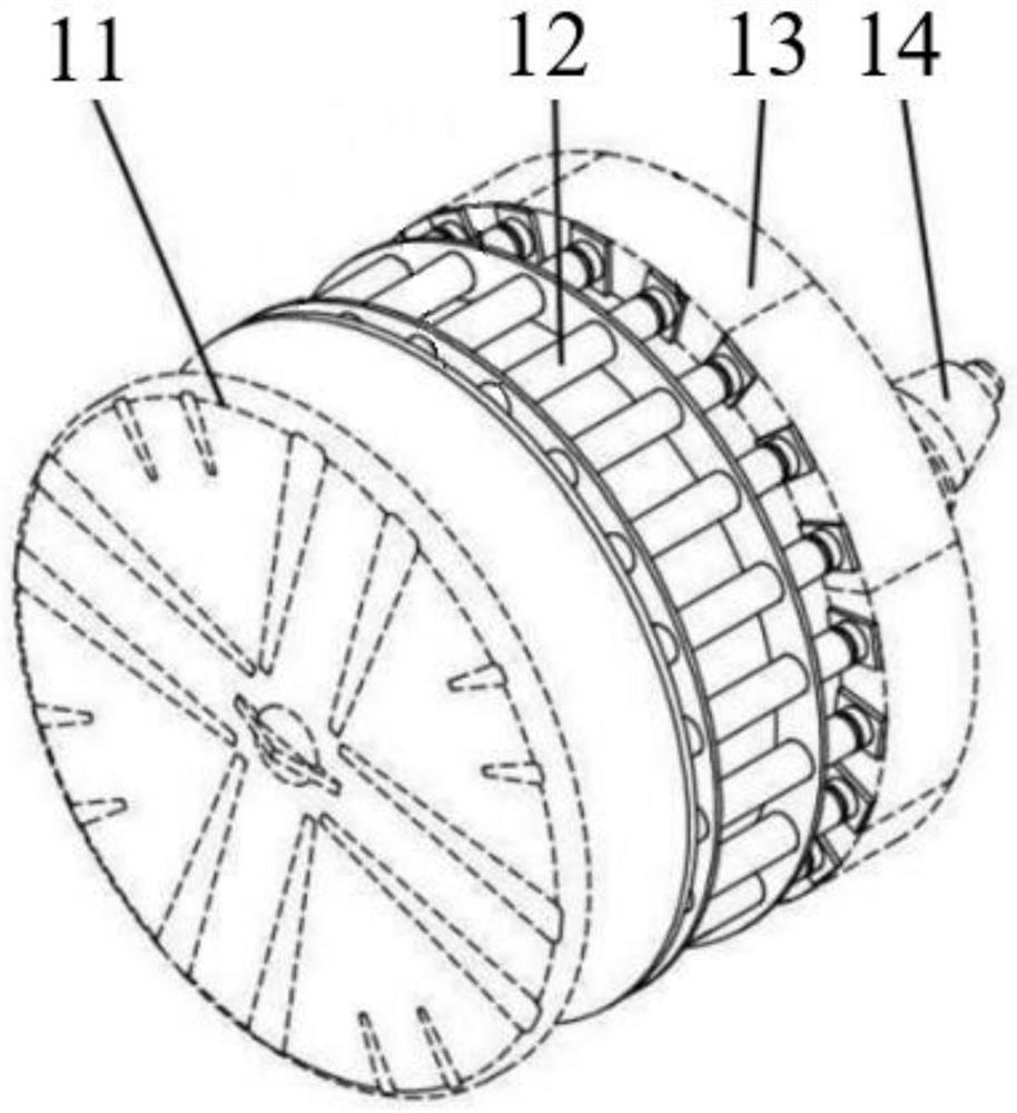
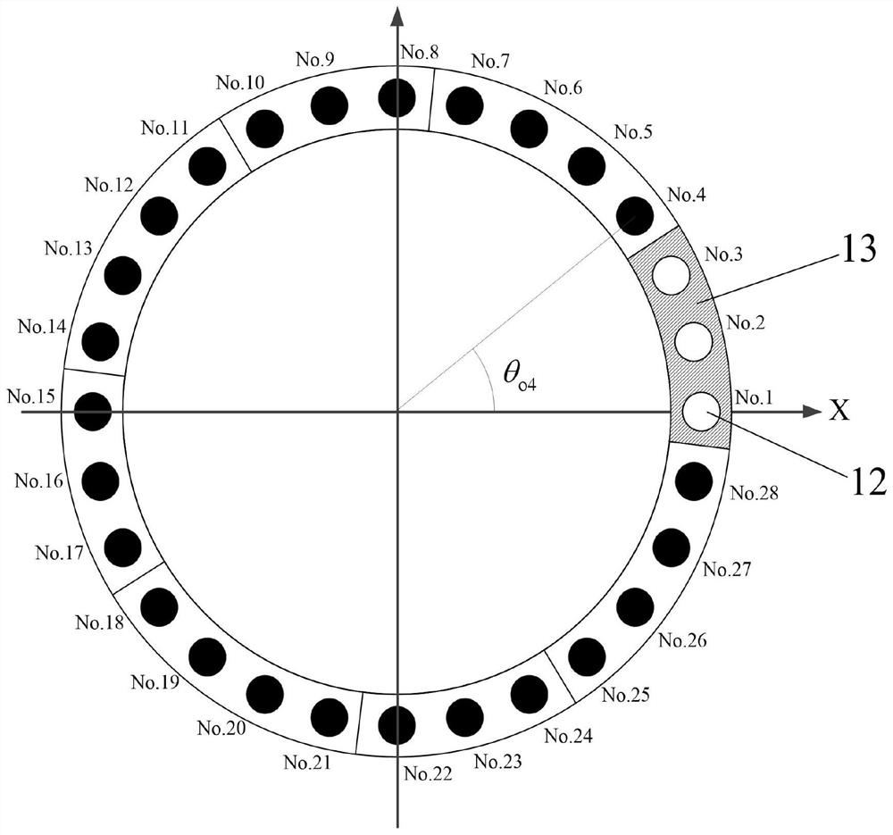
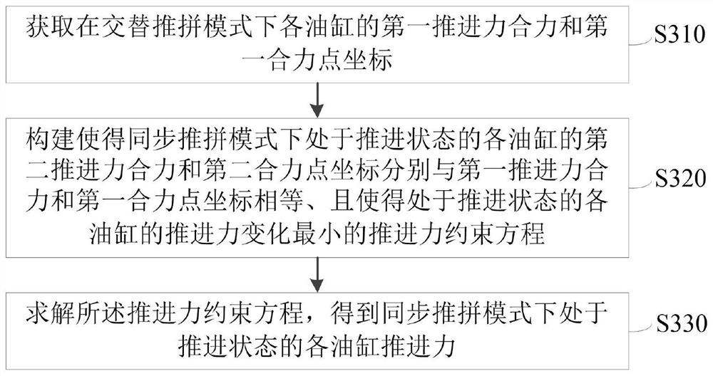

Image

  • Method, device and equipment for distributing propulsive force of synchronous pushing and splicing system of shield tunneling machine and medium
  • Method, device and equipment for distributing propulsive force of synchronous pushing and splicing system of shield tunneling machine and medium
  • Method, device and equipment for distributing propulsive force of synchronous pushing and splicing system of shield tunneling machine and medium

Examples


Embodiment Construction

[0106] The following will clearly and completely describe the technical solutions in the embodiments herein in conjunction with the accompanying drawings in the embodiments herein. Obviously, the described embodiments are only some of the embodiments herein, not all of them. Based on the embodiments herein, all other embodiments obtained by persons of ordinary skill in the art without making creative efforts fall within the scope of protection herein.

[0107] It should be noted that the terms "first" and "second" in the description and claims herein and the above drawings are used to distinguish similar objects, but not necessarily used to describe a specific order or sequence. It is to be understood that the data so used are interchangeable under appropriate circumstances such that the embodiments herein described herein can be practiced in sequences other than those illustrated or described herein. Furthermore, the terms "comprising" and "having", as well as any variations ...


PUM


Abstract

The invention provides a propulsive force distribution method, device and equipment for a synchronous pushing and splicing system of a shield tunneling machine and a medium. The method comprises the steps that first propulsive force resultant force and first resultant force point coordinates of oil cylinders in an alternate pushing and splicing mode are obtained; constructing a propulsive force constraint equation which enables the second propulsive force resultant force and the second resultant force point coordinate to be equal to the first propulsive force resultant force and the first resultant force point coordinate respectively and enables the propulsive force change of each oil cylinder in a propulsive state to be minimum; and solving the propulsive force constraint equation to obtain the propulsive force of each oil cylinder in a propulsive state in the synchronous pushing and splicing mode. On the basis of mechanics and mathematical theories, a propulsive force constraint equation which enables total propulsive force resultant force and resultant force points to be unchanged and enables propulsive force changes of all oil cylinders in a propulsive state in a synchronous pushing and splicing mode and all oil cylinders in an alternate pushing and splicing mode to be as small as possible is constructed, propulsive force loss can be reduced, adjustment of the propulsive force of all the oil cylinders is more accurate, and the propulsive force of all the oil cylinders can be adjusted more accurately. And the shield attitude and the propulsive force speed are guaranteed.

Description

technical field [0001] The invention relates to the field of shield tunnel construction technology and equipment, in particular to a propulsion distribution method, device, equipment and medium of a shield machine synchronous pushing system. Background technique [0002] Conventional shield construction adopts the alternate pushing and joining mode, that is, advance first, and then assemble the ring segment after advancing the width of one ring segment, so that the tunnel is formed at one time; after the assembly of the first ring segment is completed, the shield machine advances again A ring distance, and then a ring segment assembly, so repeated alternately. When using this mode of construction, the advancing process of the shield machine must stop completely before the assembly process can start, which leads to the frequent start and stop of the various systems of the shield machine, which fundamentally restricts the efficiency of tunnel construction. [0003] Therefore,...

Claims


Application Information

Patent Timeline
Patent Type & Authority Applications(China)
IPC IPC(8): E21D9/06E21D11/40
CPCE21D9/0607E21D11/40
Inventor 贾连辉陈力郑康泰贺开伟宋朝瑞刘睿斐林福龙焦敬波孟祥波张发亮徐淼丁红军
Owner CHINA RAILWAY ENGINEERING EQUIPMENT GROUP CO LTD
Why Eureka
Try Eureka