
Spiral clamping device for splicing building templates

A technology of building templates and clamps, which is applied to the preparation of building components on site, construction, formwork/formwork/work frame connectors, etc., which can solve the problems of increasing the difficulty of installation and disassembly, T-pin bending deformation, Damage to building formwork and other problems, to achieve the effect of convenient formwork removal, increased service life, and easy disassembly

Inactive Publication Date: 2022-03-04
刁金龙
View PDF0 Cites 0 Cited by
  • Summary
  • Abstract
  • Description
  • Claims
  • Application Information

AI Technical Summary

Problems solved by technology

[0003] At present, the template clamp uses a combination tool of T-shaped pins and triangular blocks. The principle of use is to drill holes on the frame of the template, use T-shaped pins to pass through the two template holes that need to be spliced, and then drive into the triangular block to fasten. , this formwork clamp has the disadvantages of complex installation and laborious formwork removal, and in the process of pouring concrete, the building formwork is forced to expand outwards, which is likely to cause bending deformation of the T-shaped pins, increasing installation and disassembly. Difficulty, reduce work efficiency, damage building formwork

Method used


Image

  • Spiral clamping device for splicing building templates
  • Spiral clamping device for splicing building templates
  • Spiral clamping device for splicing building templates

Examples


Embodiment Construction

[0032] The following will clearly and completely describe the technical solutions in the embodiments of the present invention with reference to the accompanying drawings in the embodiments of the present invention. Obviously, the described embodiments are only some, not all, embodiments of the present invention. Based on the embodiments of the present invention, all other embodiments obtained by persons of ordinary skill in the art without creative efforts fall within the protection scope of the present invention.

[0033] In describing the present invention, it is to be understood that the terms "opening", "upper", "lower", "thickness", "top", "middle", "length", "inner", "surrounding" etc. Indicating orientation or positional relationship is only for the convenience of describing the present invention and simplifying the description, and does not indicate or imply that the components or elements referred to must have a specific orientation, be constructed and operated in a sp...


PUM


Abstract

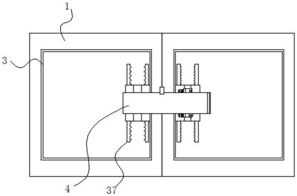
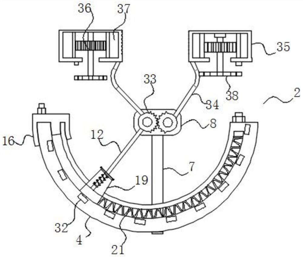
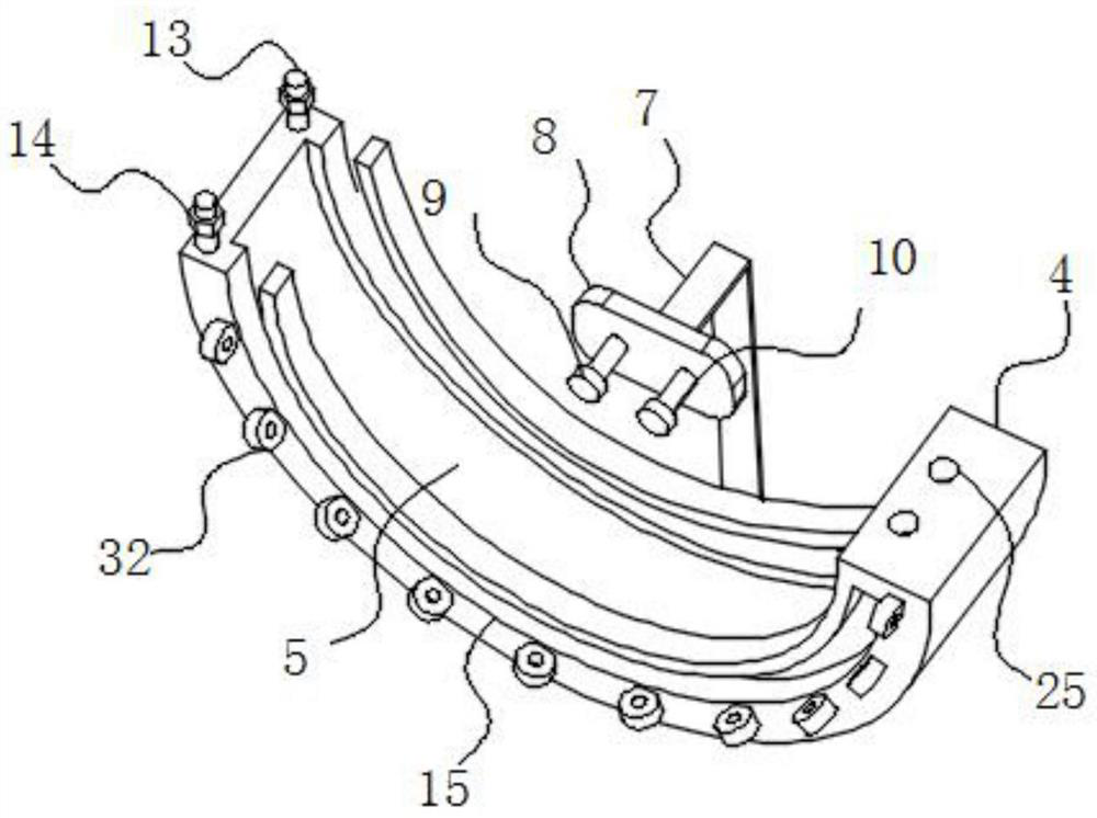
The invention discloses a spiral clamping device for splicing building templates, and relates to the technical field of building construction. The device comprises a building template and a spiral clamping device, the two building templates are clamped and fixed through the spiral clamping device; the side face of the building formwork is fixedly connected with a connecting frame. The spiral clamping device comprises an arc-shaped mounting plate; a sliding channel is formed in the inner side surface of the arc-shaped mounting plate; the sliding channel is in sliding fit with a sliding assembly. Supporting plates are fixedly connected to the side faces of the arc-shaped mounting plates. One end of the supporting plate is fixedly connected with a mounting plate; a first connecting rod and a second connecting rod are sequentially arranged on the side surface of the mounting plate; the first connecting rod and the arc-shaped mounting plate are concentrically arranged; the first connecting rod and the second connecting rod are each rotationally matched with a clamping assembly. The two C-shaped fixing plates are arranged on the side faces of the back connecting frames of the two building formworks correspondingly, the sliding assembly is rotated to drive the two missing gears to rotate synchronously in the reverse direction, the two building formworks are clamped by the clamping assembly, and mounting and dismounting are easy and convenient.

Description

technical field [0001] The invention belongs to the technical field of building construction, in particular to a spiral clamp for splicing building templates. Background technique [0002] The building formwork is a temporary support structure, which is made according to the design requirements. The back is a frame structure, so that the concrete structure and components can be formed according to the specified position and geometric size, keep their correct positions, and bear the weight of the building formwork and the action on it. The external load on the building formwork is a turnover material often used in the construction industry. When the building formwork is spliced ​​and combined, a formwork clamp should be used. [0003] At present, the template clamp uses a combination tool of T-shaped pins and triangular blocks. The principle of use is to drill holes on the frame of the template, use T-shaped pins to pass through the two template holes that need to be spliced,...

Claims


Application Information

Patent Timeline
Patent Type & Authority Applications(China)
IPC IPC(8): E04G17/00
CPCE04G17/00
Inventor 刁金龙
Owner 刁金龙
Learn More